312002282 - Structure of electrical/electronic system
Structure of electrical/electronic system
The electrical equipment on this vehicle uses the "NANO F.L.ORE.N.C.E." structure developed specifically to incorporate the most up to date electronic functions in an optimum manner.This structure makes up the car''s nervous system, directly controlling all the bodywork functions (access control, visibility, on board information, comfort, etc.) and communicates with the various chassis and power unit subsystems improving system fault diagnosis, reliability, weight and cost.A further advantage compared with traditional systems is the simplified installation through the reduction in the number of control units (for the number of functions offered to customers) and the number of power and signal connections through the extensive use of serial communication networks (3 CAN twin wire communication networks, 1 single wire LIN subnetwork, 1 A-BUS single wire subnetwork).Power distribution takes place by means of four junction units and relay/fuse boxes, connected to the control elements (static actuators and relays). These control units also act as an interconnection for the wiring and as an electrical distributor to ensure the maximum level of electrical protection and the minimum degree of wiring complexity.It is a simplified version of the previous "MINI FLORENCE" system: the structure has been simplified to manage a greater number of functions with the Body Computer.The main electronic components managed by the NANO F.L.ORE.N.C.E. structure are listed below: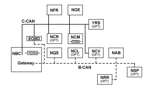
The structure of the communication lines includes:
- A 50 Kbit/s B-CAN type network. Specifications: presence of two network cables, B-CANb and B-CANa, resistant to network malfunctions; 29 bit standard
- A 500 Kbit/s C-CAN type network. Specifications: presence of two network cables, C-CANH and C-CANL, not resistant to network malfunctions; 29 bit standard
No faults present:
- The K communication lines for fault diagnosis of the C-CAN components;
- The discreet line for controlling the Engine Management Node MIL warning light; a 500 Kbit/s C-CAN type network. Specifications: presence of two network cables, C-CANH and C-CANL, not resistant to network malfunctions; 29 bit standard
- The W communication line for CODE function recovery
Components
The following components are connecte do the C-CAN:
- NBC: Body Computer Node;
- NFR: Brake Node;
- NCR: Robotised Gearbox Node (OPT);
- NGE: Electric Steering Node (OPT);
- NCM: Engine Management Node;
- YRS: Slewing Sensor Node (OPT).
Type of nodes
The following types of Nodes can be identified for the B-CAN.
- B-CAN Master +30: NBC Body Computer Node;
- B-CAN Slave +30: NQS Instrument Panel Node, NRR Radio Receiver Node (OPT).
- B-CAN Slave +30 (not time critical): NCV Convergence Node (OPT);
- B-CAN Slave +15: NCL Climate Control Node (OPT), NSP Parking Sensor Node (OPT), NAB Air Bag Node.
Whilst for the C-CAN
- C-CAN terminal node (primary): NBC Body Computer Node, NCM Engine Management Node;
- C-CAN terminal node (secondary): NCV Convergence Node (OPT)
- C-CAN nodes that allow network transit: NFR Brake Node, NGE Electric Steering Node (OPT), NCR Robotized Gearbox Node (OPT), YRS Slewing Sensor Node (OPT).
PROXY alignment
The following electronic units are subject to PROXY alignment if replaced in an after-sales service situation:
- NBC
- NQS
- NCV
- NAB.
Fault diagnosis and diagnostic connector
The diagnostic connector (EOBD connector) is outside the Body Computer Node and joins the two CANs therefore the fault diagnosis at the nodes is carried out exclusively using diagnostic messages sent via the communication networks.| It is absolutely vital to have the A16HS diagnostic connector in order to be able to converse with the various electronic units. |
The following electronic units can be diagnosed using the EXAMINER:
- NBC;
- NFR;
- NCM;
- NGE (OPT);
- NQS;
- NCV (OPT);
- NCR (OPT);
- NSP (OPT);
- NAB.
Body Computer Node
The Body Computer Node is illustrated below.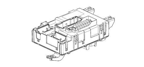
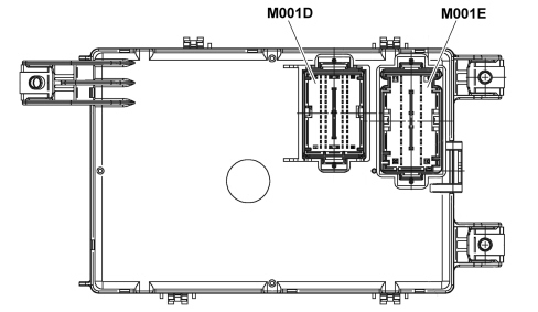
| Connector M001D PIN OUT | |
|---|---|
| Pin | Function |
| 1 | Immobilizer Aerial (Earth) |
| 2 | Immobilizer Aerial (Signal) |
| 3 | Negative signal from heated rear windscreen switch |
| 4 | F serial line for ABS / Doors LINE |
| 5 | A-bus line for rain sensor |
| 6 | Right direction indicators negative control from steering column switch unit |
| 7 | Hazard warning lights switch negative control |
| 8 | "UP" negative control on driver''s window |
| 9 | VSO signal generation |
| 10 | Hazard warning lights LED control |
| 11 | Door status LED control |
| 12 | Heated rear windscreen LED positive control |
| 13 | "DOWN" negative control on driver''s window |
| 14 | "UP" negative control on passenger window |
| 15 | "DOWN" negative control on passenger window |
| 16 | B CAN-A Air Bag Node |
| 17 | B CAN-A NRR, NCV |
| 18 | B CAN-A NQS |
| 19 | B-CAN A Diagnostic socket |
| 20 | B CAN-B NQS |
| 21 | B CAN-B Air Bag Node |
| 22 | B CAN-B NRR, NCV |
| 23 | B-CAN B Diagnostic socket |
| 24 | C CAN-H NCV (Stub) |
| 25 | C CAN-H EOBD (Stub) |
| 26 | C CAN-L NCV (Stub) |
| 27 | C CAN-L EOBD (Stub) |
| 28 | City / Sport button negative control |
| 29 | Boot internal switch signal / Tailgate (locking/unlocking) locking control switch signal |
| 30 | Front fog light switch signal |
| 31 | A/C request signal |
| 32 | Not connected |
| 33 | Reference earth to cruise lever signal |
| 34 | Reference earth to steering column switch unit signal |
| 35 | Clock spring reference earth signal |
| 36 | Main beam/flasher negative control from steering column switch unit |
| 37 | Reference earth for CSS |
| 38 | Dipped beam negative control from steering column switch unit |
| 39 | Opening/closing switch signal |
| 40 | Boot internal switch signal |
| 41 | Rear screen washer negative control from steering column switch unit |
| 42 | Horn control steering wheel 1 control |
| 43 | Opening/closing rear switch signal |
| 44 | Left direction indicators negative control from steering column switch unit |
| 45 | FN/RN control from CSS |
| 46 | Not connected |
| 47 | Not connected |
| 48 | Not connected |
| 49 | CSS reference earth |
| 50 | Radio controls on the steering wheel 2 (VOL- ; VOL+ ; Mute ; Voice) |
| 51 | Signal controlling side lights from steering column switch unit |
| 52 | Radio controls on the steering wheel 3 (SCAN - ; SCAN + ; Source ; TEL) |
| 53 | Not connected |
| 54 | Front windscreen wiper first speed negative control from steering column switch unit |
| 55 | Front windscreen washer negative control from steering column switch unit |
| 56 | Front windscreen wiper second speed negative control from steering column switch unit |
| 57 | Front windscreen wiper intermittent speed negative control from steering column switch unit |
| 58 | Not connected |
| 59 | Rearscreen wiper negative control from steering column switch unit |
| 60 | Fixed lighting controlled by the side lights for radio preparation |
| Connector M001E PIN OUT | |
|---|---|
| Pin | Function |
| 1 | INT/A from ignition switch |
| 2 | Preparation (+30) |
| 3 | Supply for Air Bag |
| 4 | Supply for radio preparation |
| 5 | Supply for Convergence |
| 6 | INT/A for CCO |
| 7 | Supply for NQS |
| 8 | Dipped headlamps positive signal for headlamp alignment control at NQS |
| 9 | Power earth 1 for NBC |
| 10 | Power earth 2 for NBC |
| 11 | INT from ignition switch |
| 12 | +30 radio power supply |
| 13 | INT Electric Window Controls Lighting |
| 14 | +30 NQS power supply |
| 15 | INT lighting CSS |
| 16 | INT additional panel for climate control / ASR button lighting |
| 17 | INT SWC Controls lighting |
| 18 | Glove compartment light |
| 19 | +30 Supply for Convergence |
| 20 | +30 for Diagnostic Socket |
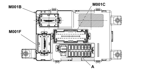
| Connector M001B PIN OUT | |
|---|---|
| Pin | Function |
| 1 | Horn relay control |
| 2 | Relay KL15 control (T6) |
| 3 | WLM window opening mechanism |
| 4 | Fog lights relay negative control |
| 5 | Door open negative signal to NCR control unit |
| 6 | Heated rear windscreen relay negative control |
| 7 | Front puddle lights |
| 8 | Right front flasher |
| 9 | Right side flasher |
| 10 | Left front flasher |
| 11 | Left side flasher |
| 12 | Left Brake Light |
| 13 | Right DRL light |
| 14 | Comfort enable supply |
| 15 | Right front side light (left and |
| ... DATA ERROR - CROPPED TEXT | Ошибка данных - Текст обрезан ... |
|---|