312002495 - 5505C26 BONNET WIRING - R.R.
| See the Wiring Diagrams section for accurate identification of the electrical connections. |
| Before working on the air bag system, it is essential to perform the following preliminary operations.(1) put the ignition key in the STOP position and extract it;(2) disconnect the battery terminals and insulate;(3) wait for at least 10 minutes before continuing. |
| FOLLOW ALL THE RECOMMENDED SAFETY INSTRUCTIONS |
| Description | Connector | |
|---|---|---|
| 1 | ENGINE FAN ADJUSTMENT HEATING COIL - 1 | See O010 ENGINE FAN ADJUSTMENT RESISTANCE - 1 |

| Description | Connector | |
|---|---|---|
| 1 | ENGINE FAN MOTOR | See N011 FAN MOTOR |

| Description | Connector | |
|---|---|---|
| 1 | SINGLE-TONE HORN | See P005 SINGLE-TONE HORN |

| Description | Connector | |
|---|---|---|
| 1 | WINDSCREEN/REARSCREEN ELECTRIC WASHER PUMP MOTOR | See N022 WINDSCREEN WASHER/ REAR WINDOW WASHER PUMP MOTOR |
| Description | Connector | |
|---|---|---|
| 2 | LINEAR SENSOR FOR FANS | See K120 LINEAR SENSOR FOR FANS |

| Description | Connector | |
|---|---|---|
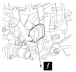
| 1 | GLOW PLUG PREHEATING CONTROL UNIT | See M015 PLUG PREHEATING CONTROL UNIT |

| Description | Connector | |
|---|---|---|
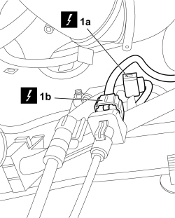
| 1a | DIFFERENTIAL PRESSURE SENSOR FAP | See K187 FAP DIFFERENTIAL PRESSURE SENSOR |
| Description | Connector | |
|---|---|---|
| 1b | DOWNSTREAM PARTICLE FILTER (DPF) TEMPERATURE SENSOR | See K190 DOWNSTREAM PARTICULATE FILTER TEMPERATURE SENSOR (DPF) |

| Description | Connector | |
|---|---|---|
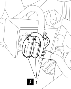
| 1 | AIR BAG FRONT SENSOR | See K039 FRONT AIR BAG SENSOR |

| Description | Connector | |
|---|---|---|
| 1a | BRAKE FLUID LEVEL SENSOR (SWITCH) | See K025 BRAKE FLUID LEVEL SENSOR (SWITCH) |
| Description | Connector | |
|---|---|---|
| 1b | BRAKING SYTEM CONTROL UNIT | See M051 Braking system control unit |

| Description | Connector | |
|---|---|---|
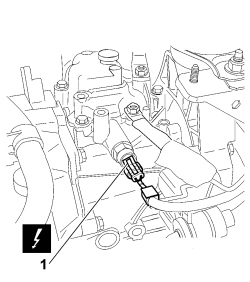
| 1 | REVERSING LIGHTS SWITCH | See I020 REVERSING LIGHTS SWITCH |

| Description | Connector | |
|---|---|---|
| 1 | LEFT FRONT WHEEL SENSOR FOR ABS | See K070 LEFT FRONT WHEEL SENSOR FOR ABS |
| Description | Connector | |
|---|---|---|
| 1 | RIGHT FRONT WHEEL SENSOR FOR ABS | See K071 RIGHT FRONT WHEEL SENSOR FOR ABS |

| Description | Connector | |
|---|---|---|
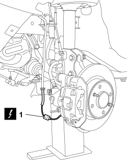
| 1 | LEFT BRAKE PAD WEAR SENSOR (SWITCH) | See K020 LEFT BRAKE PAD WEAR SENSOR (SWITCH) |
| Description | Connector | |
|---|---|---|
| 1 | LEFT FRONT DOOR COUPLING | See D030 DRIVER'S FRONT DOOR COUPLING |
| Description | Connector | |
|---|---|---|
| 1 | RIGHT FRONT DOOR COUPLING | See D031 PASSENGER FRONT DOOR COUPLING |
| Description | Connector | |
|---|---|---|
| 2 | FRONT/DASHBOARD COUPLING | See D001 FRONT/DASHBOARD COUPLING |

| Description | Connector | |
|---|---|---|
| 1 | FRONT/ENGINE COUPLING | See D004 FRONT/ENGINE COUPLING |

| Description | Connector | |
|---|---|---|
| 1 | FRONT/ENGINE COUPLING | See D004 FRONT/ENGINE COUPLING |


| Description | Connector | |
|---|---|---|
| 1a | BRAKE PEDAL SWITCH | See I030 BRAKE PEDAL SWITCH |
| Description | Connector | |
|---|---|---|
| 1b | CLUTCH PEDAL SWITCH | See I031 CLUTCH PEDAL SWITCH |
| Description | Connector | |
|---|---|---|
| 1c | ACCELERATOR PEDAL POTENTIOMETER | See K055 ACCELERATOR PEDAL POTENTIOMETER |
| Description | Connector | |
|---|---|---|
| 2 | FRONT/REAR COUPLING | See D006 FRONT/REAR COUPLING |

| Description | Connector | |
|---|---|---|
| 1a | BRAKE PEDAL SWITCH | See I030 BRAKE PEDAL SWITCH |
| Description | Connector | |
|---|---|---|
| 1b | CLUTCH PEDAL SWITCH | See I031 CLUTCH PEDAL SWITCH |
| Description | Connector | |
|---|---|---|
| 1c | ACCELERATOR PEDAL POTENTIOMETER | See K055 ACCELERATOR PEDAL POTENTIOMETER |
| Description | Connector | |
|---|---|---|
| 2 | FRONT/REAR COUPLING | See D006 FRONT/REAR COUPLING |


| Description | Connector | |
|---|---|---|
| 1 | FRONT/ENGINE COUPLING | See D004 FRONT/ENGINE COUPLING |
| Description | Connector | |
|---|---|---|
| 1 | FRONT/ENGINE COUPLING | See D004 FRONT/ENGINE COUPLING |

| Description | Connector | |
|---|---|---|
| 1 | LEFT FRONT DOOR COUPLING | See D030 DRIVER'S FRONT DOOR COUPLING |
| Description | Connector | |
|---|---|---|
| 1 | RIGHT FRONT DOOR COUPLING | See D031 PASSENGER FRONT DOOR COUPLING |
| Description | Connector | |
|---|---|---|
| 2 | FRONT/DASHBOARD COUPLING | See D001 FRONT/DASHBOARD COUPLING |

| Description | Connector | |
|---|---|---|
| 1 | LEFT BRAKE PAD WEAR SENSOR (SWITCH) | See K020 LEFT BRAKE PAD WEAR SENSOR (SWITCH) |

| Description | Connector | |
|---|---|---|
| 1 | LEFT FRONT WHEEL SENSOR FOR ABS | See K070 LEFT FRONT WHEEL SENSOR FOR ABS |
| Description | Connector | |
|---|---|---|
| 1 | RIGHT FRONT WHEEL SENSOR FOR ABS | See K071 RIGHT FRONT WHEEL SENSOR FOR ABS |

| Description | Connector | |
|---|---|---|
| 1 | REVERSING LIGHTS SWITCH | See I020 REVERSING LIGHTS SWITCH |
| Description | Connector | |
|---|---|---|
| 1a | BRAKE FLUID LEVEL SENSOR (SWITCH) | See K025 BRAKE FLUID LEVEL SENSOR (SWITCH) |
| Description | Connector | |
|---|---|---|
| 1b | BRAKING SYSTEM CONTROL UNIT | See M051 Braking system control unit |

| Description | Connector | |
|---|---|---|
| 1 | AIR BAG FRONT SENSOR | See K039 FRONT AIR BAG SENSOR |

| Description | Connector | |
|---|---|---|
| 1a | DIFFERENTIAL PRESSURE SENSOR FAP | See K187 FAP DIFFERENTIAL PRESSURE SENSOR |
| Description | Connector | |
|---|---|---|
| 1b | DOWNSTREAM PARTICLE FILTER (DPF) TEMPERATURE SENSOR | See K190 DOWNSTREAM PARTICULATE FILTER TEMPERATURE SENSOR (DPF) |
| Description | Connector | |
|---|---|---|
| 1 | GLOW PLUG PREHEATING CONTROL UNIT | See M015 PLUG PREHEATING CONTROL UNIT |
| Description | Connector | |
|---|---|---|
| 1 | WINDSCREEN/REARSCREEN ELECTRIC WASHER PUMP MOTOR | See N022 WINDSCREEN WASHER/ REAR WINDOW WASHER PUMP MOTOR |
| Description | Connector | |
|---|---|---|
| 2 | LINEAR SENSOR FOR FANS | See K120 LINEAR SENSOR FOR FANS |

| Description | Connector | |
|---|---|---|
| 1 | SINGLE-TONE HORN | See P005 SINGLE-TONE HORN |

| Description | Connector | |
|---|---|---|
| 1 | ENGINE FAN MOTOR | See N011 FAN MOTOR |

| Description | Connector | |
|---|---|---|
| 1 | ENGINE FAN ADJUSTMENT HEATING COIL - 1 | See O010 ENGINE FAN ADJUSTMENT RESISTANCE - 1 |

| Description | Connector | |
|---|---|---|
| - | BATTERY | See A001 BATTERY |