312000113 - 1080E EVAPORATION CONTROL SYSTEM
The evaporation control system is designed to prevent the fuel vapours, made up of the lightest parts of hydrocarbons that basically form in the tank, from being released into the atmosphere.The tank petrol vapours are directed by means of this system into the container housing the activated charcoal where they are absorbed.The system basically comprises the following components:
- A) Float valve
- B) Continuous breathing (multifunction) ventilation valve: it has the task of modulating the sending of the vapours to the charcoal filter via a calibrated port
- C) Activated charcoal filter
- D) Solenoid valve: it has the task of allowing the scavenging of the charcoal filter in certain engine operating conditions managed by the engine management control unit.

Float valve
These valves are used to perform the following functions:
- prevent the outflow of liquid fuel in the case of accidents where the vehicle overturns;
- allow the breathing of fuel vapours from the tank to the separator and to the active charcoal filter;
- allow tank ventilation if a vacuum builds up inside.
Full tank
If the tank is full, the float (2) blocks the opening (3) to prevent liquid fuel from reaching the separator.
Medium fuel level
If the level of the fuel in the tank decreases, the float (2) descends and rests by means of the side tabs (4) on the slots in the valve casing (1) opening the port (3) that can be reached by the gases via the ring section between the float (2) and the valve body inner seat (1). This allows the fuel vapours to leave the tank and reach the separator and the active charcoal filter or, through the same circuit, to ventilate the tank when the internal pressure is lower than the outside pressure.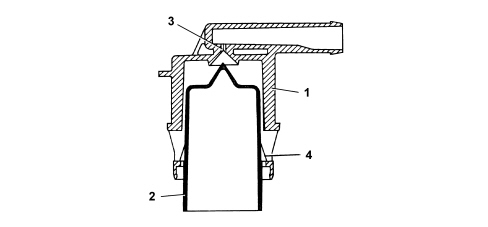
Seal in the case of roll over
If the vehicle rolls over, with the tank filled to any level, float (2) acts under its own weight and the weight of the fuel on hole (3) to prevent a dangerous outflow of fuel to the active carbon filters and the consequent risk of the vehicle catching fire.
Activated charcoal filter
Specifications
This vehicle is equipped with an active charcoal filter that includes the vapour/liquid separator.The canister has the task of absorbing the fuel vapours coming from the tank.It is fitted in the right rear wheel arch and is made up of a vegetable type active charcoal filter element.A one-way valve allows outside air (flushing air) to come in and flow over the charcoal granules to carry away the fuel vapours and convey them through the outlet to the intake manifold when fuel vapour solenoid is open.The vapour/liquid separator is designed to guarantee the separation of the liquid and gaseous parts of the fuel, reintroducing the liquid into the tank via a special pipe.
Activated charcoal filter scrubbing solenoid
Specifications
It is fitted directly on the intake manifold and is operated by the injection control unit.The solenoid allows fuel vapours stored in the canister to flow through to the engine intake.If the power is off, the solenoid is closed and prevents fuel vapours from enriching the mixture excessively.Operation
The solenoid valve is operated by the engine management control unit according to a strategy. See descriptions 1056 PETROL INJECTION SYSTEM When the electromagnet (1) is energized it attracts the shutter (2) that overcomes the load of spring pack (3) to close the port (4) and prevent fuel vapours from passing through.
Multifunction VALVE
The functions of the valve are as follows:
- tank pressurization
- fastening
- seal in the case of roll-over

Tank pressurization
Tank pressure is maintained at 30 - 45 bar using a fluorosilicon rubber valve resting on a sealing edge.The valve is supported by a stainless steel plate and held in place by a spring.When tank pressure exceeds a set level, it overcomes spring resistance and allows the valve to open so that fuel can flow out toward the canister.The valve re-closes when the pressure returns to within specified limits.Retainer
Under specific vehicle operating conditions, a vacuum develops in the tank due to:
- thermal changes
- fuel consumption
Seal in the case of roll over
The roll-over function prevents fuel emerging from the tank if the vehicle rolls over or tilts too far to one side.During normal vehicle operation (cornering, acceleration, braking etc.), the fuel may slop over into the canister.The high rollover sensitivity prevents this slop-over from occurring.The roll-over closure angle is 33°.Fuel filler cap
Operation
There is a valve is built into the fuel filler cap which, depending on fuel pressure in the tank, carries out the following functions:
- discharges the excess pressure that is created inside the tank outwards (safety function); the pressure acts on the plate (6) and, overcoming the spring (8) loading, allows the excess vapours to be discharged to the outside.
- It allows the flow of outside air into the tank when, as a result of the fuel consumption, an excessive vacuum is created in the tank (ventilation function). In this case, when the vacuum exceeds the spring (9) loading, it moves the valve (7), allowing the intake of air.
