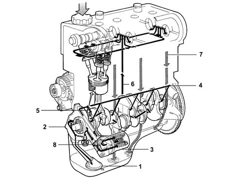
The engine lubrication circuit is illustrated in the diagram.
1. Suction head with filter mesh2. Oil pump3. Oil filter cartridge4. Main longitudinal duct5. Jets (piston skirt cooling)6. Vertical channel (camshaft mountings lubrication)7. Oil falling back into sump8. Switch for engine oil pressure warning light
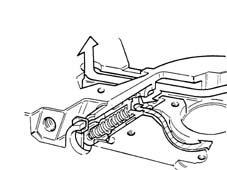
ENGINE OIL PUMP
The engine oil is drawn in by the sump by means of the vacuum created by the rotation of the gears on the crankshaft.There is a vacuum from the partition (2) for the gears as far as the oil sump suction head.Pressure builds up in all engine oil supply ducts (4) starting from separation partition (2).When the pressure exceeds 5 bar, the force exerted on limit valve (5) overcomes the reaction of the spring underneath and moves the valve until the connecting duct between pressure chamber (3) and low pressure chamber (1) opens, thereby limiting the maximum pressure value in the circuit.