312001182 - INTRODUCTION - 6 SPEED GEARBOX
CONSTRUCTION SPECIFICATIONS
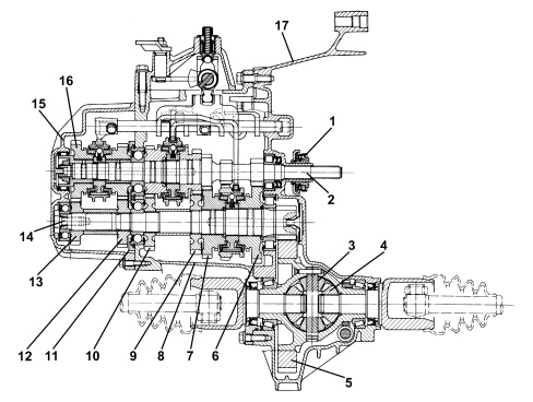
The structure of the gearbox consists of:
- a gearbox casing containing and supporting the main and layshafts, the gear engagement forks and rods and the gear selector/engagement device;
- the rear cover which contains the 5th and 6th speed gears and the bearing retaining plate for the main and layshafts;
- a casing joining the gearbox to the engine, containing the clutch, the thrust bearing and the control linkage.
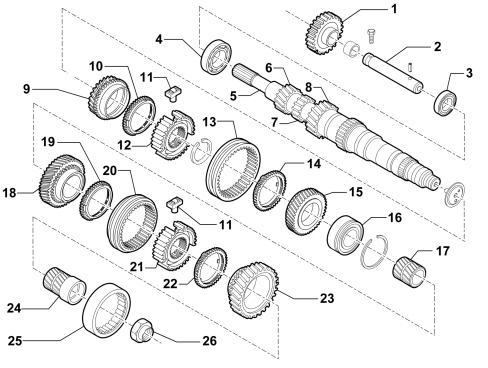
Main shaft
The main shaft consists of:
- gears for 1st and 2nd speeds and reverse formed directly on the shaft;
- gears for 3rd, 4th and 5th speeds fitted on the shaft.
Layshaft
The layshaft consists of:
- 1st, 2nd, 3rd, 4th, 5th and 6th speed gears fitted on the shaft.
The layshaft mounting consists of:
- a front roller bearing
- a rear ball bearing.
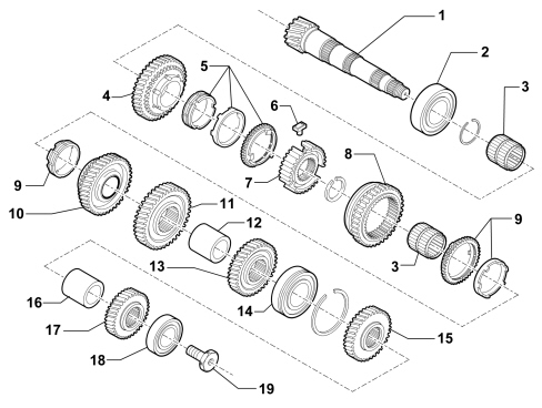
Gears
The gears are the following type:
- helical toothed for the forward gears
- straight toothed for reverse gear.
The gears and drive chain components inside the gearbox are lubricated dynamically, by means of the oil flowing along channels and through ports in the casings, the 3rd/4th speed rod and the main shaft. This allows:
- improved torque transmission and greater efficiency against the effects of wear
- manoeuvrability even at low temperatures thanks to the use of synthetic multigrade oil.
Synchronisers
The synchronisers for the forward speeds are Borg-Warner.The layout for the synchronizers is known as the split type, where the synchronizers for 1st and 2nd speeds are fitted on the layshaft, whilst those for 3rd, 4th, 5th and 6th speeds are on the main shaft.This solution reduces gearbox noise when parked in neutral because 3 of the 6 pairs of gears are not driven.The engagement and synchronization loads are also reduced as a result of the corresponding reduction in the inert rotating masses downstream of the crankshaft.The synchronizer on 1st and 2nd speeds, (the gears that are most used by the customer and thus subject to the most stress) is a double cone requiring far less engagement force than for a conventional single cone synchronizer of the same size (- 40%).A new pre-synchronizer system comprising thrust bearing blocks is used on all the gears for smoother, more positive gear shifts: in 1st and 2nd speeds the sliding gears are supported by a needle cage. The geometry of the reverse gear teeth has been improved to guarantee excellent manoeuvrability and rapid and precise engagement.Differential
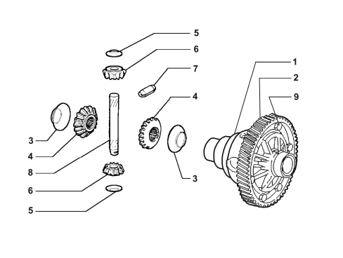
The differential unit is located in the rear part of the gearbox casing.It comprises:
- a reduction cylinder pair
- a differential housing in a single piece which incorporates the planet and satellite gears.