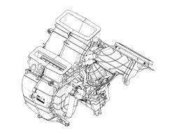
312001206 - INTRODUCTION - AIR CONDITIONING CASING AND COMPONENTS
The air conditioning casing, in other words the plastic structure fastened to the dashboard supporting crossmember, is the same on both the manual and the automatic version.The difference between the manual and automatic versions (as far as the air conditioning casing is concerned) lies exclusively in the mixture, distribution and recirculation flap movement. through flexible cables for the manual version and through electro-mechanical actuators for the automatic version.The components for the type of system are listed in the table below.| COMPONENTS | MANUAL climate control | AUTOMATIC climate control |
|---|
| Climate Control Node (NCL) | | X |
| Electro-mechanical actuators | | X |
| Compressor | X | X |
| Expansion valve | X | X |
| Radiator - heater | X | X |
| Evaporator | X | X |
| Condenser | X | X |
| Linear sensor | X | X |
| Frost sensor | X | X |
| Outside air temperature sensor | X | X |
| Passenger compartment air temperature sensor | | X |
| Mixed air temperature sensor | | X |
| Pollen filter | X | X |
| Passenger compartment fan | X | X |
| Drier filter | X | X |
ACTUATORS
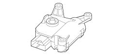
The movement of the flaps inside the automatic climate control casing, in other words the air mixing, distribution and recirculation flaps, takes place thanks to electro-mechanical actuators controlled by the NCL.The actuators contain a motor with a 12 volt power supply that controls the rotary movement of a drive pin acting directly on the flaps.A potentiometer detects the actual position of the flap and provides feedback to the control unit.The actuators are only present on the automatic climate control version. | After the control unit or one of the actuators has been replaced the self-learning procedure for the position of the flaps must be carried out using the Examiner. |
AIR DISTRIBUTION ACTUATOR
The air distribution actuator activates the rotation of the distribution flaps.It receives a 12 volt power supply and, by reversing the polarity, it can be made to rotate either clockwise or anti-clockwise. A potentiometer measures the effective position and acts as feedback for the control unit, checking the complete travel between the end of travel positions.It is fitted on the climate control casing on the pasenger sideAIR MIXING ACUATOR
It activates the rotation of the flaps for the air mixing.It is fitted on the climate control casing on the pasenger sideIt receives a 12 volt power supply and, by reversing the polarity, it can be made to rotate either clockwise or anti-clockwise. A potentiometer measures the effective position and acts as feedback for the control unit, checking the complete travel between the end of travel positions.RECIRCULATION ACTUATOR
The actuator manages the rotation of the flap in two extreme positions: dynamic (outside) air and recirculation, without intermediate positions.It is fitted in the area of the dynamic air intakeIt receives a 12 volt power supply and, by reversing the polarity, it can be made to rotate either clockwise or anti-clockwise.MIXED AIR TEMPERATURE SENSORS
There are two temperature sensors on the automatic climate control casing that provide the climate control system control unit with a signal relating to the temperature of the air coming out of the vents. One sensor is located by the FLOOR vents, the other by the centre dashboard vents.The sensors are the NTC type and feature a resistance of 10000 Ohm +/- 5% at a temperature of 25 °CFROST SENSOR
The gas flow rate control system is controlled by the climate control system control unit which acts on the compressor electromagnetic clutch depending on the temperature of the evaporator, measured by an NTC type sensor.This sensor, known as a frost sensor, is the NTC type and has the funciton of measuring the evaporator temperature.The sensor is located inside the distributor unit, fitted directly on the evaporator.It is possible, in certain circumstances, for the temperature of the evaporator to reach values that would cause the condensation on the surface of the actual evaporator to freeze. This would cause a sudden decrease in the efficiency of the climate control system; in effect, the evaporator, covered in "frost" would lose its heat exchange capacity.To prevent this from happening, if the signal produced by the frost sensor detects the danger of freezing, the operation of the compressor and consequently the circulation of refrigerant fluid is interrupted: the compressor is deactivated at temperatures < 3.5°C and reactivated at temperatures > 5°C.In the case of a manually operated system, the sensor is connected to a thermostat which is connected to the Engine Management Node which manages the switching on/off of the compressor.In the case of an automatic system, the sensor is connected directly to the Climate Control Node which communicates with the Engine Management Node via the Body Computer Node and the former switches the compressor on/off.OUTSIDE AIR TEMPERATURE SENSOR
This is an NTC sensor fitted at the bottom of the right exterior rear view mirror.It is present on both manually operated and automatic versions.It supplies a signal proportional to the temperature of the outside air.In the case of a manually operated system, the sensor sends its signal to the NQS which sends the signal to the NCM via the NBC. The NCM gives the go ahead, fir the frost sensor thermostat, for activating/deactivating the compressor. See descriptions 5010 CLIMATE CONTROL - MISCELLANEOUS In the case of an automatic signal, the sensor sends its signal to the NQS which sends the signal to the NCL via the NBC. The NCL interprets the signal and communicates with the NCM which gives the go ahead for activating/deactivating the compressor. See descriptions 5010 CLIMATE CONTROL - MISCELLANEOUS PASSENGER COMPARTMENT AIR TEMPERATURE SENSOR
This NTC type sensor has the task of notifying the climate control system management control unit of the temperature of the passenger compartment making the system able to correct the climate control parameters in order to respect the temperature set by the user.This sensor is only fitted on versions with automatic climate control.It is incorporated in the climate control system control unit and has a fan designed to prevent the build up of air inside it and make the temperature reading as consistent as possible.EXPANSION VALVE
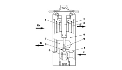
The section of the expansion valve and the main parts are illustrated in the diagram below.1. Fluid outlet duct from the evaporator2. Heat sensitive element3. To the compressor inlet connector4. Pressurized fluid5. Opposing spring6. Ball and calibrated port7. Expanded fluid (at the evaporator inlet connector)8. Valve body9. RodC. To the compressorF. From the drier filterEi. Evaporator inletEu. Evaporator outletThe tasks of this valve are to:
- Separate the high pressure circuit from the low pressure circuit;
- Expand the refrigerant (change in state from liquid to gas);
- Regulate the evaporation process (flow rate);
- Regulate the evaporation temperature;
- Protect the compressor from refrigerant fluid.
The thermostatic expansion valve is fitted on the evaporator inlet and outlet ducts with the task of regulating the flow and expansion (drop in pressure) of the R134a fluid before entry into the evaporator.The automatic regulation of the size of the passage for the gas inside the expansion valve is produced by a sensitive bulb which measures the temperature of the refrigerant fluid and depending on this suitably adjusts the size of the opening that the gas passes through by means of a special spring that moves a shutter determining the extent of the expansion.The increase in temperature at the evaporator outlet, detected by the bulb, ensures that the valve is opened with a consequent increase in the flow rate of the fluid in the evaporator.Conversely, low temperatures involve a reduction in the size of the gas port determining a decrease in the flow of gas. | The valve regulation screw is calibrated during production and should NOT be tampered with to avoid adversely affecting the efficiency of the air conditioning system. |
The expansion valve is directly accessible from the engine compartment.This type of expansion valve has two different refrigerant fluid flows:
- Lower flow from point (4), gas coming from drier filter, to point (7), outlet of gas to the evaporator, containing the heating spring (5) and the modulating element which in this case is the ball (6) housed in the calibrated duct.
- Upper flow, from point (1), gas coming from the evaporator, to point (3), outlet of gas to the compressor, containing the thermostatic sensor (2) which is connected to the top part of the diaphragm and to the ball (6).
The control function for the flow rate is exerted by the movement of the ball (6), connected, via the rod (9), to the thermostatic sensor (2).The action of the ball (6) is opposed by the suitably calibrated spring (5) which ensures that the refrigerant fluid in the evaporator is in a gaseous state without the presence of any liquid which, if drawn in by the compressor, could damage it.The position of the ball (6) depends on the difference in pressure acting on the diaphragm located inside the sensor (2); this, in turn, depends on the outlet temperature of the refrigerant fluid from the evaporator (upper flow for the valve).High temperatures for the gas coming out of the evaporator (1) corresponding to high heat dissipation conditions increase the pressure inside the thermostatic sensor (2); this involves the movement of the rod (9) and the ball (6) connected to it, increasing the section of the passage and, as a result, the flow rate of the refrigerant (7).The reverse is true if the temperature of the gas coming out of the evaporator (1) is low.LINEAR PRESSURE SWITCH
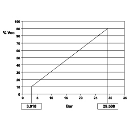
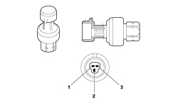
The linear pressure switch controls the correct operation of the system replacing the task performed by the quadrinary pressure switch. By continuously analyzing the pressure of the climate control system circuit, the sensor provides the engine management control unit, in real time, wih the variations in pressure making the management of the activation levels more flexible.For each variation in pressure there is a corresponding voltage signal used by the engine management control unit to activate the fan speed and switch off the compressor if the pressure increases or decreases beyond the permitted limits (safety function).The operating range of the linear sensor goes from 3.018 bar up to 29.508 bar according to the following pressure (bar) / output voltage percentage (%Vcc) curve.LINEAR PRESSURE SWITCH
The go ahead for the activation of the compressor and the adjustment of the fan speed, depending on the variation in pressure, takes place in this pressure range; the compressor is deactivated above and below these values for safety reasons to prevent damage to the system.The pin out for the sensor is illustrated in the diagram below: | The supply voltage can vary by ±10% and the temperature of the sensor is between -5°C and 80°C. |
1. Earth2. Supply voltage3. Output signalCOMPRESSOR
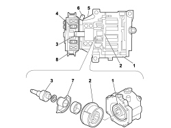
Using the mechanical energy from the engine via the electromagnetic clutch and pulley, this machine allows the circulation of the refrigerant in the circuit varying the pressure level.The compressor is the same for both the manual and automatic versions.DENSO SCS06 compressor specifications:
- max continuous number of revs: 8450 rpm.
- max non-continuous number of revs: 10000 rpm.
- scroll radius: 4.58 mm
- Quantity of lubricant: 50 cm[sup3 ].
The compressor is the scroll type with a system that ensures deactivation when the temperature of the evaporator reaches values close to freezing. The deactivation signal is operated by the frost sensor fitted on the evaporator.Scroll compressors have a fixed casing 1 and a moving casing 2.The movement of the camshaft (3) connected to the pulley creates a chamber whose volume decreases during rotation allowing its compression.1. Fixed casing2. Scroll3. Camshaft4. Ball bearing5. Guard6. Compressor power supply electric connection7. Balancing mass8. PulleyThe contact between the compressor fixed casing and the moving casing creates a chamber whose volume decreases gradually when the moving casing rotates.The compression chamber is alternately open for the supply of gas, closed for moving it and then open at the outlet connector for discharging the gas under pressure.The pressure of the gas stored, defined by the volume produced by the two casings (one fixed and the other moving), increases gradually until the gas reaches the centre area where it reaches operating pressure; here the gas is discharged via the outlet connector to t| ... DATA ERROR - CROPPED TEXT | Ошибка данных - Текст обрезан ... |
|---|