312001893 - 5540 EXTERIOR LIGHTING
COMPOSITION
The vehicle components and their location are illustrated below.
1. Front direction indicator2. Left upper front light cluster3. Left lower front light cluster4. Left fog lamp5. Right fog lamp6. Right lower front light cluster7. Right upper front light cluster8. Headlamp alignment adjustment on instrument panel9. Centre Control Panel10. Left rear light cluster11. Right rear light cluster12. Third brake light13. Number plate lightsThe vehicle exterior lighting system has been designed and produced with two objectives in mind:
- guaranteeing maximum efficiency with regard to the international regulations that define the lighting technology specifications for the various components;
- being integrated with the design of the vehicle so that the various components enhance the image.
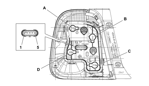
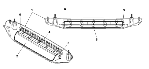
REAR LIGHT CLUSTER
The vehicle exterior lighting system has been designed and produced with two objectives in mind:
- Guaranteeing maximum efficiency with regard to the international regulations that define the lighting technology specifications for the various components.
- Being integrated with the design of the vehicle so that the various components enhance the image.
The external appearance is that of a one-piece multicoloured unit. A functional decision was taken to fit a one-piece light cluster.The light cluster carries out the following lighting functions:
- Side light and brake light incorporating red colour.
- Orange direction indicators.
- 1 red rear fog lamp (left)
- 1 clear car reversing light (right)
A. P21W Brake light 12W – 21WB. PY21W Direction indicator 12W - 21WC. P21W Reversing light 12V- 21W (right side only), Reversing light 12V-21W (left side only)D. R10W Side lights 12V- 10W| CONNECTOR PIN OUT |
|---|
| 1 | Position |
| 2 | Brake light |
| 3 | Earth |
| 4 | Reversing light/Rear fog lamp |
| 5 | Direction indicator |
Number plate light
The number plate light function is achieved by means of two light clusters fitted using a metal clip and a reference fastened to the panel.Each light is fitted with an all-glass C5W bulb (12V - 5W) and should be replaced by removing the light cluster from the panel and the bulb holder from the number plate light, incorporated in the wiring in the rear bumper.Upper front light cluster structure (dipped headlights)
The unit consists of:A. Direction indicatorsB. Dipped beam lampsC. Headlight horizontal axis manual adjustment screwD. Direction indicators rear coverE. Headlight vertical axis manual adjustment screwF. Dipped beam lamp rear coverG. Connector| CONNECTOR PIN OUT |
|---|
| 1 | Not connected |
| 2 | Not connected |
| 3 | Direction indicator positive |
| 4 | Dipped beam positive |
| 5 | Earth (for headlamp and light adjustment) |
| 6 | Headlamp alignment corrector positive |
| 7 | Headlamp alignment corrector signal |
| 8 | Not connected |
Bulbs present:
- H7LL halogen bulb for dipped headlights function 12V-55W
- WY21W for direction indicators function 12V-21W
The front light cluster is a lamp constructed from a fixed lens reflection technology for all the functions (dipped headlight and main beam headlight).The headlight includes the dipped beam function and the direction indicator. The corrector is located inside the body. The bulb is accessed by removing the cap at the rear of the headlight body.The lens cover is made from colourless lacquered CR 120-600 polycarbonate that has undergone scratch-resistant treatments; it is fastened to the casing by means of butyl sealant which should ensure a water-tight seal. It has the task of guaranteeing uniform, standardized brightness without light seeping outside of the dedicated area.The frame is made from metallic PA80-100.The headlight body is made from black PP 70-20 polypropylene with a 40% talc content, treated in the drip channel area to allow bonding between body and lens. The cap seat, the connector seat, the light beam adjustment systems seats, and the breather plug seats are located at the rear.Inside are the seats for the alignment corrector, reflector fastenings, and various hooks.The fastening system is made up of three brackets with slots on the metallic inserts. The type approval mark and customer logo are stamped on the headlight upper bracket.The dipped beam and direction indicator reflector is made from BMC LPR 20 with aluminium reflecting surface.The dipped beam and direction indicator reflector is made from metallic BMC LPR20 thermosetting material with a clear protective coating or equivalent treatment. It is equipped with connections for the fixed point and for horizontal/vertical adjustment so that the light beam does not vibrate even when the road surface is uneven.Seats for the bulb holders with retaining clips are provided. The bulb holder seat is polarised to prevent incorrect positioning of the bulb.2 bolts are used for adjustment. Adjustments can be made with the bonnet open using a size 12 jointed hexagonal wrench. The adjustment angles are: manual vertical ± 3° (to compensate for light beam body tolerances), electrical vertical to compensate for alignment variations (2° 30''), horizontal ±1° 30''.Electrically controlled headlamp alignment corrector
The headlamp alignment device is designed to adjust dipped light beam correctly in a vertical direction irrespective of the load on the axles.When the ignition key is turned to the MAR position the instrument panel (NQS) does not display either the position (0, 1, 2, 3) or the symbol until the dipped headlights are switched on.The condition that appears is the last value memorized when the key was turned from MAR to STOP.With the dipped headlamps on, using the buttons on the side of the instrument panel, it is possible to alter the angle/direction of the light cluster in 4 standard positions: the following loads correspond to the four positions:Position 0. one or two persons on the front seats.Position 1. four persons.Position 2. four persons + load in the luggage compartment.Position 3. driver + maximum permitted load stowed in the luggage compartment.The maximum load refers to: the maximum permitted load on the rear axle or: the total permitted load for the vehicle. The weight of a person is taken as 75 kg.The instrument panel display shows the position in relation to the adjustment set. See descriptions 5560 INSTRUMENTS The headlamp incorporates an electric motor: the latter controls the position by means of a pinion and an adjustment screw suitably tilting the dipped headlamp reflector.1. Headlamp alignment correction electric motor2. Dipped headlamp reflector3. Headlight vertical axis manual adjustment screwOperation and adjustment (headlamp alignment)
When the key is turned to MAR (key on) and the dipped beam headlights are on, pressing the two adjustment buttons on the frame of the instrument panel alters the angle/direction of the light cluster in 4 standard positions. The positions are stored and displayed on the instrument panel display together with the respective symbol.In practice, when the instrument panel node receives the increase (CAF+) or decrease (CAF-) signal from the buttons, it checks, by means of a control and adjustment module, whether there is a positive power supply for the dipped headlamps and if this is the case it produces and sends an adjustment signal to the electronics for the headlamp alignment motors. The output signal from the instrument panel (NQS) electronics is a maximum voltage value for position (0) decreasing for the subsequent positions (1-2-3) with an identification level that makes it possible to operate the actuator incorporated in the light cluster for moving the parabola.Voltage values are shown below according to the selected position:
- Position 0: 90% of power supply voltage
- Position 1: 85% of power supply voltage
- Position 2: 82% of power supply voltage
- Position 3: 79% of power supply voltage
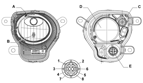
No adjustments can be made with the ignition key in the STOP position (key off).Prolonged pressing of the adjustment buttons does not cause a progressive change.Disconnecting the battery or resetting the system causes the value memorized to be lost and the value predefined by the manufacturer, in this case zero (0) is adopted (predefined = default = standard).Lower front light cluster structure (main beam headlamp)
The unit consists of:A. Main beam headlightsB. Side lightC. Headlight vertical axis manual adjustment screwD. Lights rear coverE. Connector| CONNECTOR PIN OUT |
|---|
| 1 | Not connected |
| 2 | Not connected |
| 3 | DLR positive for side light |
| 4 | Main beam positive |
| 5 | Earth |
| 6 | Side light positive |
| 7 | Not connected |
| 8 | Not connected |
Bulbs present:
- H1 halogen bulb for main beam headlights function 12V-55W
- W21 for side lights function 12V-5W
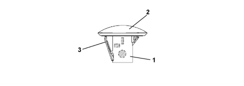
Adjustment of light beam orientation is via a screw. Adjustments can be made from the front wheel compartment using a size 12 jointed hexagonal wrench.The manual vertical adjustment angle is ± 3°.SIDE DIRECTION INDICATOR LIGHT
The side repeater is illustrated below.1. Case2. Colourless lens cover3. Securing springThe side light is fitted with the following bulb type: 5W5 12V- 5W in orange.To replace the small bulb, push the lens cover manually in the opposite direction to the vehicle''s direction of travel in order to compress fastening clip (3). Release the front section and extract the unit. Rotate the bulb holder in an anti-clockwise direction and extract it from the lens coverADDITIONAL BRAKE LIGHT
The additional brake light function is performed by a multi-bulb light and a light beam emerging from the rear window screen printing on the upper part of the tailgate trim to create a lit area.1. Case2. Lens cover3. Clip4. Bulb holder body5. All-glass bulb W5W 12V- 5W6. Connector seatThe outer casing is made from a grey coloured plastic material and contains the bulb holder which is in one piece and fastened to the lamp casing. The internal current strips are in brass and supply 5 small all-glass 12V - 5W bulbs when powered.The lamp is secured to the tailgate by two bolts; the light casing is secured to the outer shell by two bolts.SWITCHING ON BRAKE LIGHTS (LEFT/RIGHT)
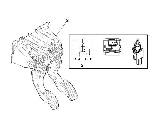
Brake light switch PIN OUT.A. Signal for Body Computer (n.o.) connector M001B pin 27 and third brake light power supplyB. From dashboard control unit fuse F37 (key switch) (from M001C pin 7)C. From dashboard control unit fuse F51 (key switch) (from M001C pin 25) (for versions with robotized gearbox)D. Signal for Body Computer (n.c.) connector M001B pin 34 (for versions with robotized gearbox)1. Brake switch seat on pedal unit2. Electrical diagram of connector with pedal pressedThe brake light function is activated with the ignition key in the MAR position (INT) with voltage.Position of switch C-D normally closed (n.c.) with pedal releasedPosition of switch A - B normally open (n.o.) with pedal releasedWhen the pedal is pressed:
- a voltage signal is supplied to the Body Computer Node, which thereby recognizes that the brake pedal is not in the rest position (pedal released) and it supplies the brake lights
- the third brake light is powered directly when the brake pedal switch contact is closed
The Body Computer Node is capable of recognizing the following faults:
- Open circuit (at key-on when command issued): absence of bulb is indicated,
- Short circuit to +VB (at key-on when command issued): bulb fault is indicated.
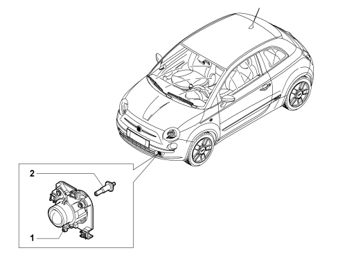
FOG LAMPS
The fog lights are located in the lower part of the front bumper. The unit has a screw for adjusting the direction of the light beam.1. Fog lamp light cluster2. HI 12V 55W bulbCENTRE CONTROL SWITCH UNIT PANEL
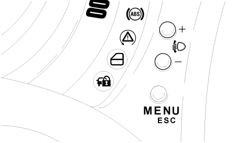
The central control panel is a control module located on the centre console and connected to the dashboard cable, which supplies the power to illuminate the icons, and it houses the following controls:
- Sport (where supplied) / City for electrical guide
- emergency and direction indicator lights
- fog lights
| ... DATA ERROR - CROPPED TEXT | Ошибка данных - Текст обрезан ... |
|---|