312001895 - 5550A STALK UNIT
INTRODUCTION
The diagram shows the steering wheel stalk unit.
COMPONENTS AND OPERATION
The casing
The casing is the part of the steering column switch unit that contains the electrical circuits and the switching and automatic release mechanisms which return the left (direction) lever to the rest position, following the realignment of the steering wheel, after a manoeuvre has been carried out.
Electronic module
This is the electronic control unit which controls the wiper functions and it is mechanically fastened to the casing to which it is connected electrically by means of special terminals.It controls the operation of the:
- Windscreen wiper: Sweep rate;
- Rearscreen wiper: Sweep rate and control during reversing;
- Windscreen wiper function: Smart washing;
- Rear washer function: Smart washing;
Clock spring
It has two functions:
- transmitting the rotation of the steering wheel to the automatic release mechanism located inside the casing;
- to transfer the electrical signal for the controls on the steering wheel (horn and other optional services) and the Air Bag module.
Multifunction switch or right lever
Includes lighting and turn signal controls.All the controls are activated by operating either the stalk or the wheel control on the end of the stalk.
The control is operated anticlockwise and offers 2 fixed positions:
- Pos. 5 = No circuit on (or DRL lights on if fitted)
- Pos. 6 = Side lights + low/high beam enablement + rear fog lamp.
Multifunction switch or left lever
This includes the front and rear wiper controls. All the controls are activated by operating either the stalk or the wheel control on the actual lever. A button on the end of the stalk switch also controls trip computer functions.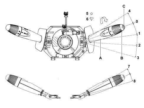
This is operated by moving the lever in the same plane as the steering wheel. The control can be operated to 5 different positions:
- Pos. 0 = No circuit activated (STABILE): POS. REST;
- Pos. 1 = Intermittent (STABLE): CLOCKWISE DIRECTION;
- Pos. 2 = Continuous 1st SPEED (STABLE): CLOCKWISE DIRECTION;
- Pos. 3 = Continuous 2nd SPEED (STABLE): CLOCKWISE DIRECTION;
- Pos. 4 = Antipanic function (UNSTABLE): ANTICLOCKWISE DIRECTION;
The control offers 2 STABLE positions and is moved clockwise:
- Pos. 5 = No circuit operated;
- Pos. 6 = Rear wiper operated;
The following activate the rearscreen wiper:
- Specific rearscreen wiper command from the steering column switch unit;
- Engagement of reverse with windscreen wiper activated.
Electronic module (built into steering wheel stalk unit)
This is the electronic control unit that controls the operation of the electric motors, the windscreen wipers and the rearscreen wiper and the washing functions and it is mechanically fastened to the casing to which it is electrically connected by means of dedicated terminals.In particular, it controls the operation of:
- Winscreen wiper (Sweep rate for all specifications);
- Rear wiper (Sweep rate and control during reversing);
- Screen washer function (Smart washing on all specifications);
- Rear washer function (Smart washing on all specifications)
Steering column switch unit electronic module pin out
The connectors in the steering column switch unit module are illustrated in the diagram below
| Connector H005A pin out | |
|---|---|
| Pin | Function |
| 1 | Negative signal from trip computer button |
| 2 | Intermittent rearscreen wiper negative signal to NBC |
| 3 | N.C. |
| 4 | Rear windscreen washer pump control negative signal to NBC |
| 5 | N.C. |
| 6 | Windscreen washer pump/ headlamp washer control negative signal to NBC |
| 7 | Intermittent windscreen wiper negative signal to NBC |
| 8 | 1st speed windscreen wiper negative signal to NBC |
| 9 | 2nd speed windscreen wiper/antipanic negative signal to NBC |
| Connector H005B pin out | |
|---|---|
| Pin | Function |
| 1 | N.C. |
| 2 | Reference earth from NBC |
| 3 | Left direction indicators/parking lights control negative signal to NBC |
| 4 | Right direction indicators/parking lights control negative signal to NBC |
| 5 | Main beam headlamps flasher negative signal to NBC |
| 6 | Dipped headlights negative signal to NBC |
| 7 | Side lights control negative signal to NBC |
| 8 | N.C. |
| 9 | N.C. |
| Connector D047 pin out | |
|---|---|
| Pin | Function |
| 1 | preparation |
| 2 | preparation |
| 3 | Steering wheel controls input 1 (scan +/-, source, telephone) |
| 4 | Steering wheel controls input 2 (volume +/-, mute, voice) |
| 5 | Steering wheel controls lighting |
| 6 | Earth for analogue signals and steering wheel controls lighting earth |
| 7 | Horn earth |
| 8 | Horn |
| 9 | Driver''s Air Bag stage 2 + |
| 10 | Driver''s Air Bag stage 2 - |
| 11 | Driver''s Air Bag stage 1 + |
| 12 | Driver''s Air Bag stage 1 - |
| Connector A pinout | |
|---|---|
| Pin | Function |
| 1 | Driver''s Air Bag + |
| 2 | Driver''s Air Bag - |
| Connector B pin out | |
|---|---|
| Pin | Function |
| 1 | Steering wheel controls input 1 (scan +/-, source, telephone) |
| 2 | Steering wheel controls lighting |
| 3 | Horn earth |
| 4 | Horn |
| 5 | Steering wheel controls input 2 (volume +/-, mute, voice) |
| 6 | N.C. |
| 7 | Earth for analogue signals and steering wheel controls lighting earth |
| 8 | N.C. |