312002000 - 5580H PARKING OBSTACLE DETECTION DEVICE
Parking sensors system
The Parking Assistance system provides the driver with information on distance when approaching obstacles behind the vehicle thereby providing help with parking manoeuvres and identifying obstacles that are outside the field of vision.The information on the presence/distance of an obstacle is transmitted to the driver by means of acoustic warnings whose frequency depends on the distance of the obstacle.Composition
The parking assistance system comprises the following components:
- parking sensors electronic management control unit
- four ultrasonic sensors
- connection to the B-CAN (with the Body Computer Node)
- connection to the B-CAN. (between the Body Computer Node and the Instrument Panel Node)
The buzzer on this version is inside the instrument panel.Parking sensor control unit
The control unit is an electronic component that provides the driver with assistance during manoeuvres with reverse gear engaged by recognizing any obstacles to the rear.The electronic control unit carries out the following functions:
- Activating the sensors,
- Processing the signals received by the sensors,
- Checking the operation of the sensors,
- Activating the buzzer in the instrument panel,
- Managing the fault diagnosis and test functions.
The electronic control unit has a device that protects against voltage fluctuations and short circuits.The control unit and pin out are illustrated in the diagram below| Connector A |
|---|
| Pin | Signal |
| 1 | Ignition-operated power supply |
| 2 | n.c. |
| 3 | n.c. |
| 4 | n.c. |
| 5 | Presence of trailer |
| 6 | n.c. |
| 7 | B-CAN A |
| 8 | Earth |
| 9 | n.c. |
| 10 | n.c. |
| 11 | n.c. |
| 12 | n.c. |
| 13 | n.c. |
| 14 | B-CAN B |
| 15 | n.c. |
| 16 | n.c. |
| Connector B |
|---|
| Pin | Signal |
| 1 | Sensor earth |
| 2 | Right rear inner sensor signal |
| 3 | Left rear inner sensor signal |
| 4 | Right rear outer sensor signal |
| 5 | Left rear outer sensor signal |
| 6 | n.c. |
| 7 | n.c. |
| 8 | n.c. |
| 9 | n.c. |
| 10 | n.c. |
| 11 | n.c. |
| 12 | Sensor positive |
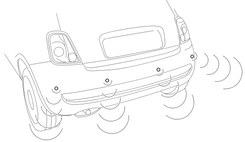
Sensors
The sensors are incorporated in the bumper using special adaptors (covers).The sensors use ultrasound technology and act as intelligent transmitters/receivers with a triangulation technique: they allow improved detection in critical situations or in the presence of small obstacles. The impulses emitted are reflected by any obstacles; the transducer receives an echo which is converted into a digital signal and sent to the electronic control unit.| Sensor pin out |
|---|
| Pin | Signal |
| 1 | Sensor signal |
| 2 | Earth |
| 3 | Sensor power supply |
The operation of the sensors is automatically deactivated when the pin for the trailer electric cable is inserted in the vehicle tow hook socket.Operation
The sensor is an ultrasound transducer which acts as an intelligent transmitter and receiver of ultrasound impulse packages. Both the frequency and the voltage of the impulses are produced in the transducer.The impulses emitted are reflected by any obstacles; the transducer therefore receives an echo which is amplified and converted into a digital signal, sent to the electronic control unit via the same line used for the transmission request.Each sensor can also be operated as a receiver only, in order to be able to take a triangular measurement between two sensors. This technique allows better detection both of small obstacles and in situations featuring critical reflection.The sensors all have the same electrical and mechanical properties; the maximum detection distance for each sensor can be adjusted using software according to the location of the actual sensor.Detection distances
Centre operating range 120cmSide operating range 60 cmIf the sensors detect several obstacles, only the closest one is taken into consideration.Measuring distance of obstacles
The electronic control unit controls the sensors, which convert the control unit electrical signals into ultrasound impulses at a rhythm which varies between 3 and 10 measuring processes per second.The signal, reflected by any obstacles, is received by the sensor and amplified by it, converted into a digital signal and sent, in this format, to the electronic control unit.The control unit compares the signal transmitted with the one received and, using suitable algorithms, calculates the time elapsed between the issue of the signal and the reception of the echo. This information is translated into distance and the driver is notified by means of acoustic signals. | Reflections from the ground are ignored unless they have the characteristics of an obstacle |
Self-diagnosis
The control unit carries out a self-diagnostic test when it is switched on. The sensors are diagnosed each time they are activated.Recovery strategies
The sensors and the wiring are subject to continuous fault diagnosis while the system is operating. A fault in only one sensor inhibits the operation of the entire system.Activation and deactivation of the system
When the control unit is switched on (vehicle key-on and reverse gear engaged) a self-diagnostic test and a test on all the peripheral functions is carried out. The system is ready to use in under 0.5 seconds.The measurement of the distance only takes place when the system is activated.The system is activated when the following two conditions are verified:
- Key ON
- Reverse gear engaged
When the system is activated the buzzer in the instrument panel sounds as a warning that the system is activated.If obstacles are present, it signals the distance of the obstacle by means of impulses whose frequency increases as the vehicle gets closer to the obstacle.If there is a problem with the system then a warning signal is emitted.Obstacle distance signal
The sound from the buzzer warns the driver that the vehicle is approaching an obstacle. The sound lasts for 75 ms, whilst the pause between the sounds is directly proportional to the distance of the obstacle: impulses in quick succession indicate the presence of an obstacle that is very close. A continuous sound indicates that the obstacle is less than 30 cm away.The tone cycle remains constant if the distance measured by the control unit sensors remains unaltered.Error signalling
Any faults/errors are also signalled acoustically.The acoustic signal stops after 3 seconds.The occurrence of errors/faults whilst the system is active is signalled immediately.