323000322 - INTRODUCTION - ANTI-LOCK BRAKING SYSTEM (A.B.S.)
CONSTRUCTION SPECIFICATIONS
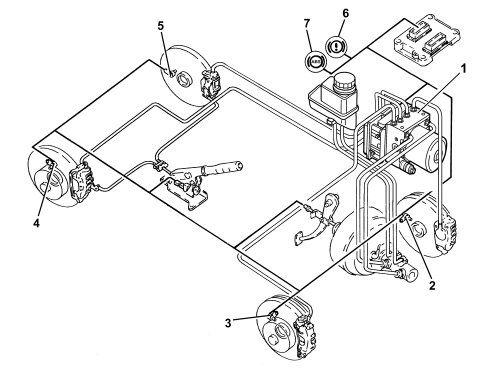
The vehicle is equipped with an ABS/EBD brake control system.The ABS/EBD system is the Bosch 8.1 type, developed from the ABS system already used on other vehicles.The ABS is fitted parallel to the hydraulic braking system so that should it not work braking would still be guaranteed.The ABS includes the EBD function (Electronic Brake Force Distribution), the electronic adjustment and distribution of the braking force between the axles. There is therefore no mechanical device on the braking system for distributing the brake force between the two axles.VIEW OF ASSEMBLY
1 - ABS/EBD control unit2 - Left front wheel sensor3 - Right front wheel sensor4 - Right rear wheel sensor5 - Left rear wheel sensor6 - EBD warning light7 - ABS warning light
SPECIFICATIONS
The Bosch 8.1 ABS control unit is a cutting-edge version, connected to the C-CAN network. It is known as the BSM (Brake System Module) and comes in two versions:- With EBD- With EBD and ESP (Electronic Stability Program) which includes the ASR/MSR/HBA/HHC functions.The ABS control unit is connected to the front wiring; the system cable loom is incorporated in the engine compartment cable loom.The control unit receives and transmits information on the C-CAN
COMPOSITION
Structure
The Bosch 8.1 A.B.S. system consists of:- an electronic control unit integrated with the hydraulic control unit;- a hydraulic control unit that modulates braking pressure by means of eight solenoids, two for each wheel;- four ACTIVE MAGNETORESISTIVE sensors that record wheel angular speed of rotation;- wiring with specific connector
OPERATION
Introduction
The electronic control unit processes signals from the active sensors and brake light control switch. It identifies the wheel or wheels with a tendency to lock (maximum slip between wheel and road surface) by means of the control unit software, and modulates the brake fluid pressure selectively for the front wheels and in tandem for the rear wheels (select-low function).The ABS modulates brake pressure in accordance with three basic stages:- 1st pressure maintenance stage;- 2nd pressure reduction stage;- 3rd pressure increase stage.If operation is requested, the ABS stays active at speeds greater than 2.7 km/h. After that, it cuts out to allow the car to stop.After the key ON and when a speed of 6 km/h is exceeded, the control unit carries out an operation check on the solenoids and pump motor. The control unit also tests the sensors when a speed of 12 km/h is exceeded.The ABS is detected as a component of the C-CAN network by the body computer at the first key ON.
Operating strategies
Pressure increase stage without intervention of ABSWhen the brake pedal is pressed, the electronic control unit (1):- does not supply charge solenoid (N.O.) (2)- does not supply discharge solenoid (N.C.) (3)The pressure generated by the brake pump (4) therefore reaches the brake callipers (5) without undergoing changes.
Intervention of ABSPressure maintenance stageThe electronic control unit (1):- supplies charge solenoid (N.O.) (2)- does not supply discharge solenoid (N.C.).The hydraulic connection between brake pump (4) and brake calliper (5) is therefore broken.The pressure in the brake calliper (5) remains constant even when pressure on the brake pedal is increased.
Pressure reduction stageThe electronic control unit:- supplies charge solenoid (N.O.) (2)- supplies discharge solenoid (N.C.) (3).The hydraulic connection between brake pump (4) and brake calliper (5) is broken and discharge solenoid (3) opens and brings brake calliper (5) into communication with low pressure accumulator (6) and scavenger pump (7).Control unit (1) also supplies motor (8), driving scavenger pump (7) to return fluid taken from brake calliper (5) to the main circuit.The fluid flows through high pressure accumulator (9) and restriction (10), which performs a damping function.The system is equipped with a check valve (11) fitted in parallel with charge solenoid (2) which allows fast reduction of pressure in brake calliper (5) during brake pedal release stage.
Pressure increase stageThe electronic control unit (1):- does not supply charge solenoid (N.O.) (2)- does not supply discharge solenoid (N.C.) (3)The fluid taken into the main circuit is then free to return to the brake calliper (5) and increase the pressure acting on the brake calliper.
EBD function (electronic brake force distribution)The EBD function controls brake force distribution and thus replaces the conventional mechanical load proportioning valve, allowing:- acts exclusively on the rear brakes- improved brake force distribution- optimal intervention under all load conditions (static or dynamic), driving conditions (straight line or corners) or car condition (tyres, brakes and suspension)- implementation of a strategy that follows the ideal distribution curve.
Fa - Front axle brake forceFp - Rear axle brake forceA - Distribution curve implemented by the brake systemB - Ideal distribution curveC - Distribution curve implemented by a conventional hydraulic load proportioning valveD - Distribution curve implemented by the EBD functionEBD function failure is indicated by simultaneous activation of:- ABS warning light- low brake fluid and/or handbrake-on warning light.Under these conditions, the car must be driven with extreme caution to the nearest authorised workshop to have the system checked.RecoveryThe electronic control unit comes with a safety circuit which monitors ABS efficiency.With the ignition key inserted, the safety circuit carries out an initial auto test for 4 seconds to check:- electronic control unit operation- solenoid operation (activates these to check them)- control of the C-CANEvery time the car starts off from a standstill, the safety circuit checks for signals from active sensors.When the car is in motion, the safety circuit works as follows:- continually compares wheel angular speed with the calculated reference speed- checks memory condition- checks operation of the relays, the solenoids and the pump motor- constantly monitors battery voltage- checks C-CAN efficiencyIf the safety circuit detects one or more faults in system components during the check stage, the safety circuit operates as follows:- deactivates the ABS while still guaranteeing operation of the conventional braking system- indicates the fault status to the driver by turning on a warning light on the control panel.