323002064 - 1016E10 SINGLE CYLINDER HEAD, REMOVED - OVERHAUL
| Tool | Description | Function | Validity |
|---|---|---|---|
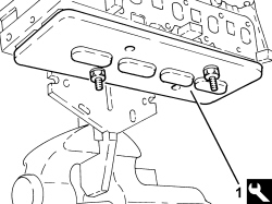
| 1860470000 | Mount | Head overhaul |


| Tool | Description | Function | Validity |
|---|---|---|---|
| 1870896900 | Templates | Engine tuning | 1.3 Multijet |
| Measurement | Value | Validity |
|---|---|---|
| Camshaft end float (mm) | 0.15 ÷ 0.34 | 1.3 Multijet |
| Fit the tool, positioning it with the millings in a horizontal direction and checking that it is correctly inserted in the camshaft housing. |
| Tool | Description | Function | Validity |
|---|---|---|---|
| 1870896900 | Templates | Engine tuning | 1.3 Multijet |

| Tool | Description | Function | Validity |
|---|---|---|---|
| 1870896900 | Templates | Engine tuning | 1.3 Multijet |

| Tool | Description | Function | Validity |
|---|---|---|---|
| 1860470000 | Mount | Head overhaul |


| Tool | Description | Function | Validity |
|---|---|---|---|
| 1860749000 | Stand | Valve support | 1.4 8v |
| Tool | Description | Function | Validity |
|---|---|---|---|
| 1860644001 | Lever | Removing/ refitting valves | 1.4 8v1.3 Multijet |
| Tool | Description | Function | Validity |
|---|---|---|---|
| 1870881000 | Chamber | Removing/ refitting valves | 1.3 Multijet |

| Tool | Description | Function | Validity |
|---|---|---|---|
| 1860749000 | Stand | Valve support | 1.4 8v |
| Tool | Description | Function | Validity |
|---|---|---|---|
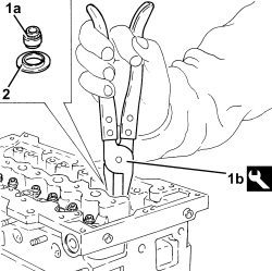
| 1870894000 | Calliper | Removing valve guide oil seals | 1.3 Multijet |
| Measurement | Value | Validity |
|---|---|---|
| Cylinder head lower surface flatness (mm) | 0.1 | 1.3 Multijet |
| When within limit conditions (head gasket with 2 notches before levelling), the cylinder head lower surface cannot be levelled. |
| Measurement | Value | Validity |
|---|---|---|
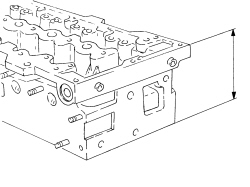
| Cylinder head nominal height (mm) | 105.5 +/- 0.05 | 1.3 Multijet |
| Measurement | Value | Validity |
|---|---|---|
| Valve stem/inlet valve diameter - exhaust (mm) | 5.90 ÷ 5.94 | 1.3 Multijet |
| Measurement | Value | Validity |
|---|---|---|
| Valve spring free length (mm) | 37.9 | 1.3 Multijet |
| Measurement | Value | Validity |
|---|---|---|
| Length of valve springs under a load of 16.2 - 18.0 daN (mm) | 31.0 | 1.3 Multijet |
| Measurement | Value | Validity |
|---|---|---|
| Length of valve springs under a load of 36.1 - 39.5 daN (mm) | 23.5 | 1.3 Multijet |
| Measurement | Value | Validity |
|---|---|---|
| Camshaft bearing diameter - First bearing (mm) | 38.500 ÷ 38.515 | 1.3 Multijet |
| Measurement | Value | Validity |
|---|---|---|
| Camshaft bearing diameter - Second bearing (mm) | 38.000 ÷ 38.015 | 1.3 Multijet |
| Measurement | Value | Validity |
|---|---|---|
| Camshaft bearing diameter - Third bearing (mm) | 30.000 ÷ 30.015 | 1.3 Multijet |
| Measurement | Value | Validity |
|---|---|---|
| Nominal inlet cam lift (mm) | 6.4 | 1.3 Multijet |
| Measurement | Value | Validity |
|---|---|---|
| Nominal exhaust cam lift (mm) | 7.5 | 1.3 Multijet |
| Measurement | Value | Validity |
|---|---|---|
| Camshaft support diameter - First support | 38.545 ÷ 38.570 | 1.3 Multijet |
| Measurement | Value | Validity |
|---|---|---|
| Camshaft support diameter - Second support | 38.045 ÷ 38.070 | 1.3 Multijet |
| Measurement | Value | Validity |
|---|---|---|
| Camshaft support diameter - Third support | 30.045 ÷ 30.070 | 1.3 Multijet |

| Measurement | Value | Validity |
|---|---|---|
| Valve seat band angle in contact with valve | 45° +/- 20’ | 1.3 Multijet |

| Tool | Description | Function | Validity |
|---|---|---|---|
| 1860470000 | Mount | Head overhaul |
| Tool | Description | Function | Validity |
|---|---|---|---|
| 1860749000 | Stand | Valve support | 1.4 8v |
| Tool | Description | Function | Validity |
|---|---|---|---|
| 1870900800 | Installing tool | Valve guide oil seal fitting | 1.3 Multijet |

| Tool | Description | Function | Validity |
|---|---|---|---|
| 1860644001 | Lever | Removing/ refitting valves | 1.4 8v1.3 Multijet |
| Tool | Description | Function | Validity |
|---|---|---|---|
| 1870881000 | Chamber | Removing/ refitting valves | 1.3 Multijet |

| Tool | Description | Function | Validity |
|---|---|---|---|
| 1860749000 | Stand | Valve support | 1.4 8v |
| Component | Fastening | dia | Value (daNm) | Validity |
|---|---|---|---|---|
| Intake manifold | Bolt | M8 | 2.3 ÷ 2.8 | 1.4 8v |
| Component | Fastening | dia | Value (daNm) | Validity |
|---|---|---|---|---|
| Exhaust gas/water heat exchanger for E.G.R. system | Bolt | M8 | 2.3 ÷ 2.8 | 1.3 Multijet |
| Component | Fastening | dia | Value (daNm) | Validity |
|---|---|---|---|---|
| Switch for engine oil pressure warning light | - | M14 | 2.9 ÷ 3.5 |
| Component | Fastening | dia | Value (daNm) | Validity |
|---|---|---|---|---|
| Thermostat | Bolt | M8 | 2.2 ÷ 2.7 | 1.3 Multijet |
| Before fitting the locating bushes, check that the height is 13 mm. |
| Position the hydraulic tappets with the oil channel hole turned toward the outside of the cylinder head: this position brings the hole into communication with the oil duct on the lower cylinder head. |
| Tool | Description | Function | Validity |
|---|---|---|---|
| 1860470000 | Mount | Head overhaul |
| Component | Fastening | dia | Value (daNm) | Validity |
|---|---|---|---|---|
| Glow heater plug | - | M8 | 0.9 ÷ 1.1 | 1.3 Multijet |
| Component | Fastening | dia | Value (daNm) | Validity |
|---|---|---|---|---|
| Exhaust manifold to cylinder head | Nut | M8 | 1.4 ÷ 1.6 +30° ± 3° | 1.3 Multijet |
| Tool | Description | Function | Validity |
|---|---|---|---|
| 1860470000 | Mount | Head overhaul |
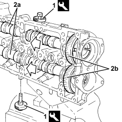
| Fit the tools and position with their millings in a horizontal direction. Ensure they fit into the seats on the camshafts. |
| Tool | Description | Function | Validity |
|---|---|---|---|
| 1870896900 | Templates | Engine tuning | 1.3 Multijet |
| Component | Fastening | dia | Value (daNm) | Validity |
|---|---|---|---|---|
| Camshaft gears | Bolt | M12 | 13.5 ÷ 16.5 | 1.3 Multijet |

| Component | Fastening | dia | Value (daNm) | Validity |
|---|---|---|---|---|
| Cam angle sensor | Bolt | M6 | 0.64 ÷ 0.96 | 1.3 Multijet |
| Component | Fastening | dia | Value (daNm) | Validity |
|---|---|---|---|---|
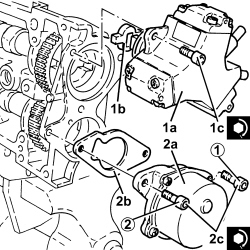
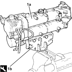
| Pressure pump | Bolt | M7 | 1.4 ÷ 1.7 | 1.3 Multijet |
| Component | Fastening | dia | Value (daNm) | Validity |
|---|---|---|---|---|
| Vacuum unit | Bolt | M8 | 1.8 ÷ 2.2 | 1.3 Multijet |
| Follow the order shown in the diagram for each tightening sequence. The tightening to 2.0 daNm is performed in two stages: a pre-tightening to 0.5 daNm followed by an additional tightening of 1.8 - 2.2 daNm. |