- Connect the positive probe of the Examiner in voltmeter mode to terminal 1 of the flow meter and the negative probe to terminal 2 of the earth.- With the ignition on, check that the voltage measured is 12 Volts.
Air flow rate signal check
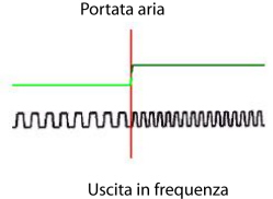
Connect using the Examiner in voltmeter mode with the positive probe at terminal 4 of the flow meter and the negative probe at the earth and follow the progress of the air flow rate signal with an oscilloscope; it should have an amplitude of 5 Volts and variable frequency: there should be a corresponding increase in the frequency of the output signal from the flow meter for an increase in the intake air flow rate (and consequently a decrease in the value of the period)
T = Output voltageP = Air flow rate
Air temperature signal check
Check that the temperature signal sent to the engine management control unit is a PWM type duty cycle signal (with a fixed frequencey). The operating voltage is 5 Volts and the measurement interval is between -50 and 150°C (with a consequent duty cycle value of between 10% and 90%
Air temperature signal.
Air flow meter
Flow meter pin out
Pin 1 12 Volt supplyPin 2 earthPin 3 air temperature output signalPin 4 air earth output signal