323002078 - 1056B90 SYSTEM CABLE LOOM - R.R.
| Description | Connector | |
|---|---|---|
| 2 | Timing sensor | See K047 TIMING SENSOR |
| Description | Connector | |
|---|---|---|
| 3 | Ignition coil | See A030 IGNITION COIL |

| Description | Connector | |
|---|---|---|
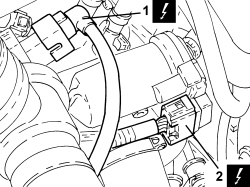
| 1 | Turbocharging sensor | See K082 SUPERCHARGING SENSOR |
| Description | Connector | |
|---|---|---|
| 2 | Lambda sensor on preconverter | See K015 LAMBDA SENSOR ON PRE-CATALYZER |
| Description | Connector | |
|---|---|---|
| 3 | Lambda sensor on catalytic converter | See K017 LAMBDA SENSOR ON CATALYZER |

| Description | Connector | |
|---|---|---|
| 1 | Engine coolant temperature sensor/sender unit | See K036 ENGINE COOLANT TEMPERATURE SENSOR/SENDER UNIT |

| Description | Connector | |
|---|---|---|
| 1 | Integrated throttle body actuator | See N075 BUILT-IN THROTTLE BODY ACTUATOR |
| Description | Connector | |
|---|---|---|
| 2 | Turbocharger by-pass solenoid | See L102 TURBOCHARGER BY-PASS SOLENOID VALVE |
| Description | Connector | |
|---|---|---|
| 1 | Waste gate solenoid | See L037 WASTE GATE SOLENOID VALVE |

| Description | Connector | |
|---|---|---|
| 2 | Air pressure - temperature sensor | See K044 AIR TEMPERATURE/PRESSURE SENSOR |

| Description | Connector | |
|---|---|---|
| 1 | Injector coupling | See D081 INJECTOR JUNCTION |
| Description | Connector | |
|---|---|---|
| 2 | Fuel vapour recovery solenoid valve | See L010 FUEL VAPOUR RECOVERY SOLENOID VALVE |

| Description | Connector | |
|---|---|---|
| 1 | Engine oil pressure sensor (switch). | See K030 ENGINE OIL PRESSURE SENSOR (SWITCH) |
| Description | Connector | |
|---|---|---|
| 2 | Rpm sensor | See K046 RPM SENSOR |

| Description | Connector | |
|---|---|---|
| 1 | Knock sensor | See K050 DETONATION SENSOR |

| Description | Connector | |
|---|---|---|
| 1 | Air conditioning compressor engagement solenoid | See L021 AIR CONDITIONING COMPRESSOR ENGAGEMENT SOLENOID VALVE |

| Description | Connector | |
|---|---|---|
| 1 | Engine cables/engine services cable coupling | See D029 ENGINE CABLES/ENGINE SERVICES CABLE COUPLING |
| Description | Connector | |
|---|---|---|
| 2 | Engine management control unit | See M010 ENGINE MANAGEMENT ECU |

| Description | Connector | |
|---|---|---|
| - | ENGINE MANAGEMENT CONTROL UNIT | See M010 ENGINE MANAGEMENT ECU |
| Description | Connector | |
|---|---|---|
| - | ENGINE CABLE/ENGINE SERVICE CABLE COUPLING | See D029 ENGINE CABLES/ENGINE SERVICES CABLE COUPLING |
| Description | Connector | |
|---|---|---|
| - | AIR CONDITIONING COMPRESSOR ENGAGEMENT SOLENOID | See L021 AIR CONDITIONING COMPRESSOR ENGAGEMENT SOLENOID VALVE |
| Description | Connector | |
|---|---|---|
| - | DETONATION SENSOR | See K050 DETONATION SENSOR |
| Description | Connector | |
|---|---|---|
| - | RPM SENSOR | See K046 RPM SENSOR |
| Description | Connector | |
|---|---|---|
| - | ENGINE OIL PRESSURE SENSOR (SWITCH) | See K030 ENGINE OIL PRESSURE SENSOR (SWITCH) |
| Description | Connector | |
|---|---|---|
| - | FUEL VAPOUR RECOVERY SOLENOID | See L010 FUEL VAPOUR RECOVERY SOLENOID VALVE |
| Description | Connector | |
|---|---|---|
| - | INJECTOR COUPLING | See D081 INJECTOR JUNCTION |
| Description | Connector | |
|---|---|---|
| - | AIR PRESSURE/TEMPERATURE SENSOR | See K044 AIR TEMPERATURE/PRESSURE SENSOR |
| Description | Connector | |
|---|---|---|
| - | WASTEGATE SOLENOID | See L037 WASTE GATE SOLENOID VALVE |
| Description | Connector | |
|---|---|---|
| - | TURBOCHARGER BY-PASS SOLENOID | See L102 TURBOCHARGER BY-PASS SOLENOID VALVE |
| Description | Connector | |
|---|---|---|
| - | INTEGRATED THROTTLE CASING ACTUATOR | See N075 BUILT-IN THROTTLE BODY ACTUATOR |
| Description | Connector | |
|---|---|---|
| - | ENGINE COOLANT TEMPERATURE SENSOR/SENDER UNIT | See K036 ENGINE COOLANT TEMPERATURE SENSOR/SENDER UNIT |
| Description | Connector | |
|---|---|---|
| - | LAMBDA SENSOR ON CATALYTIC CONVERTER | See K017 LAMBDA SENSOR ON CATALYZER |
| Description | Connector | |
|---|---|---|
| - | LAMBDA SENSOR ON CATALYTIC PRECONVERTER | See K015 LAMBDA SENSOR ON PRE-CATALYZER |
| Description | Connector | |
|---|---|---|
| - | SUPERCHARGING SENSOR | See K082 SUPERCHARGING SENSOR |
| Description | Connector | |
|---|---|---|
| - | IGNITION COIL | See A030 IGNITION COIL |
| Description | Connector | |
|---|---|---|
| - | TIMING SENSOR | See K047 TIMING SENSOR |