| STEP | CHECK TO BE PERFORMED | REMEDIAL ACTION IF THE CHECK IS NOT OK |
|---|
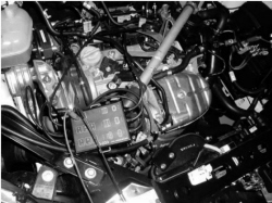
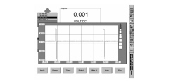
| 1 | Injection signal checkPrepare the diagnostic equipment for a voltage graph assimilation. Select the "VOLTMETER" function from the "INSTRUMENT" menu with the time set at 1 second.Connect the probes between the pins of the injector that is not working (using disconnector AD 233 N° 1806387000). Press the START button on the diagnostic equipment to begin downloading a graph. Let the engine be driven and check that the signal corresponds to the enclosed graph | Renew the wiring between the engine management control unit and the injectors. If the signal is interrupted at the control unit output replace the engine management control unit Op. 1056B82 INJECTION/IGNITION SYSTEM E.C.U. (ONE) - R + R |
| 2 | Injector power supply checkCheck that the injectors are correctly suppliedMove on to Step 3 | Renew the 15A fuse F22 in the engine compartment junction unit after having identified the cause of the problem. Restore the correct power supply for the injectors |
| 3 | Injector resistance checkDisconnect the injector connectorConnect the Examiner in ohmmeter mode between the injector terminals and then check the resistance: the value should be 12 Ohm ± 10% at 20°C | Replace the injector Op. 1056B70 INJECTOR (ONE) - R + R WITH FUEL MANIFOLD PIPE REMOVED - INCLUDES SEAL REPLACEMNT |