323001628 - 1004E10 ENGINE, REMOVED - REMOVE CYLINDER HEAD AND OIL SUMP FOR INSPECTION - INCLUDES POSITIONING ON STAND AND REMOVAL
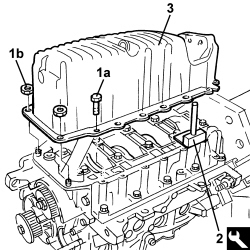
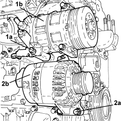
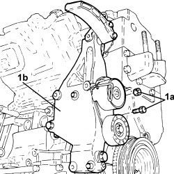
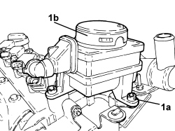
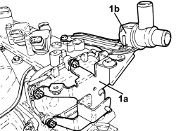
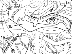
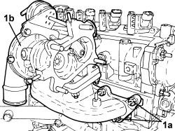
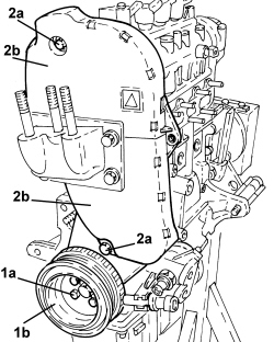
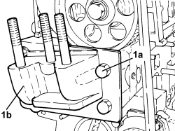
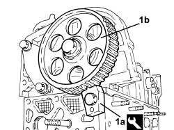
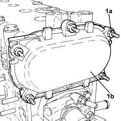
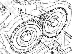
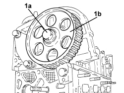
1. Undo bolts (1a) and remove timing belt inner guard (1b).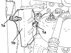
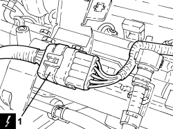
| Description | Connector | |
|---|---|---|
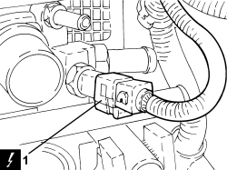
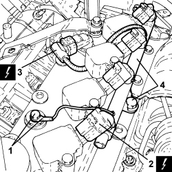
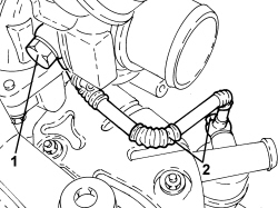
| 1 | Rpm sensor | See K046 RPM SENSOR |
| Description | Connector | |
|---|---|---|
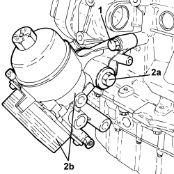
| 2 | Engine oil pressure sensor (switch) | See K030 ENGINE OIL PRESSURE SENSOR (SWITCH) |
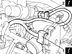
| Description | Connector | |
|---|---|---|
| 1 | Air pressure - temperature sensor | See K044 AIR TEMPERATURE/PRESSURE SENSOR |
| Description | Connector | |
|---|---|---|
| 2 | Air conditioning compressor engagement solenoid | See L021 AIR CONDITIONING COMPRESSOR ENGAGEMENT SOLENOID VALVE |
| Description | Connector | |
|---|---|---|
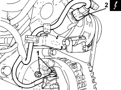
| 1 | Injector coupling | See D081 INJECTOR JUNCTION |
| Description | Connector | |
|---|---|---|
| 1 | Knock sensor | See K050 DETONATION SENSOR |
| Description | Connector | |
|---|---|---|
| 2 | Fuel vapour recovery solenoid valve | See L010 FUEL VAPOUR RECOVERY SOLENOID VALVE |
| Description | Connector | |
|---|---|---|
| Integrated throttle body actuator | See N075 BUILT-IN THROTTLE BODY ACTUATOR |
| Description | Connector | |
|---|---|---|
| 2 | Turbocharger by-pass solenoid | See L102 TURBOCHARGER BY-PASS SOLENOID VALVE |
| Description | Connector | |
|---|---|---|
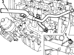
| Engine coolant temperature sensor/sender unit | See K036 ENGINE COOLANT TEMPERATURE SENSOR/SENDER UNIT |
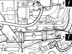
| Description | Connector | |
|---|---|---|
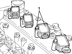
| 2 | Ignition coil | See A030 IGNITION COIL |
| Description | Connector | |
|---|---|---|
| 3 | Timing sensor | See K047 TIMING SENSOR |


| Tool | Description | Function | Validity |
|---|---|---|---|
| 2000015800 | Counter-torque | Camshaft driven pulley lock | 1.4 16v TJET |
| Tool | Description | Function | Validity |
|---|---|---|---|
| 1860834000 | Spanner | Loosen/tighten the cylinder head extension bolts | 1.4 16v TJET |
| Tool | Description | Function | Validity |
|---|---|---|---|
| 1860988000 | Tappet retaining tool | Tappet retaining | 1.4 16v TJET |
| Tool | Description | Function | Validity |
|---|---|---|---|
| 1870718000 | Blade | Cut sealant |