323002054 - 1004E20 ENGINE - DISMANTLE AND REASSEMBLE FOLLOWING OPERATION 1004E10 - WASH AND CHECK DISMANTLED PARTS - REFIT CYLINDER HEAD AND OIL SUMP - DOES NOT INCLUDE REPAIRS TO CYLINDER HEAD AND AUXILIARY UNIT
| Tool | Description | Function | Validity |
|---|---|---|---|
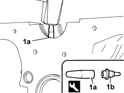
| 1870718000 | Blade | Cut sealant |
| Tool | Description | Function | Validity |
|---|---|---|---|
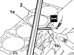
| 2000004500 | Template | Crankshaft timing | 1.4 8v1.4 16v TJET |
| Tool | Description | Function | Validity |
|---|---|---|---|
| 1860815000 | Flange | Crankshaft rotation | 1.3 Multijet1.4 16v TJET |
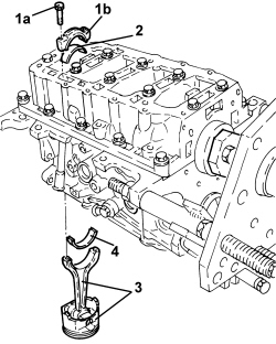
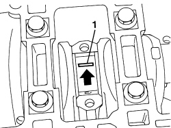
| The arrow on the piston crown facing the timing side indicates the fitting direction.The matching of the connecting rod-cap is the "BREAKING" type therefore the position is compulsory and the number corresponding to the position of the cylinder must be present. |
| Measurement | Value | Validity |
|---|---|---|
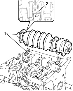
| Crankshaft endfloat (mm) | 0.155 ÷ 0.355 | 1.4 16v T-JET |
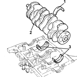
| If the value for the crankshaft endfloat does not correspond with the recommended figures, when refitting, regrind the crankcase seat and use the central main bearing half incorporating appropriately oversized crankshaft thrust half-washers. |
| Tool | Description | Function | Validity |
|---|---|---|---|
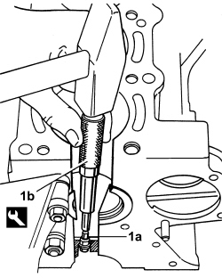
| 1860395000 | Striker | Engine oil jet removal | 1.4 8v1.4 16v TJET |
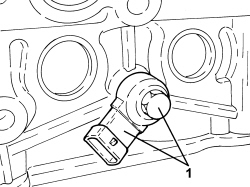
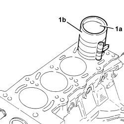
| Insert the drift guide hole on the nozzle surface to prevent the drift from slipping and damaging the cylinder liner during the removal operation. |
| Use new oil jets when refitting. |
| Tool | Description | Function | Validity |
|---|---|---|---|
| 1860313000 | Fitting tool | Engine oil jet fitting | 1.4 8v1.4 16v TJET |
| Measurement | Value | Validity |
|---|---|---|
| Cylinder head support surface flatness (mm) | < 0.1 | 1.4 8v1.4 16v T-JET |
| Measurement | Value | Validity |
|---|---|---|
| Cylinder liner diameter - Grade A (mm) | 72.000 ÷ 72.010 | 1.4 8v1.4 16v T-JET |
| Measurement | Value | Validity |
|---|---|---|
| Cylinder liner diameter - Grade B (mm) | 72.010 ÷ 72.020 | 1.4 8v1.4 16v T-JET |
| Measurement | Value | Validity |
|---|---|---|
| Cylinder liner diameter - Grade B (mm) | 72.010 ÷ 72.020 | 1.4 8v1.4 16v T-JET |
| Measurement | Value | Validity |
|---|---|---|
| Cylinder liner ovality (mm) | +/- 0.05 | 1.4 8v1.4 16v T-JET |
| Measurement | Value | Validity |
|---|---|---|
| Cylinder liner taper (mm) | +/- 0.005 | 1.4 8v1.4 16v T-JET |
| In the case of reaming, all the liners must have the same oversize. |
| Measurement | Value | Validity |
|---|---|---|
| Cylinder liner diameter oversize (mm) | 0.1 | 1.4 8v1.3 Multijet1.4 16v T-JET |
| Measurement | Value | Validity |
|---|---|---|
| Main journal diameter - Category A (mm) | 47.994 ÷ 48.000 | 1.4 16v T-JET |
| Measurement | Value | Validity |
|---|---|---|
| Main journal diameter - Category B (mm) | 47.988 ÷ 47.994 | 1.4 16v T-JET |
| Measurement | Value | Validity |
|---|---|---|
| Main journal diameter - Category C (mm) | 47.982 ÷ 47988 | 1.4 16v T-JET |
| Because the crankshaft has undergone nitriding, this treatment should be repeated and the size re-checked if it is ground. |
| Measurement | Value | Validity |
|---|---|---|
| Main journal diameter undersize (mm) | 0.127 | 1.4 8v1.3 Multijet1.4 16v T-JET |
| Measurement | Value | Validity |
|---|---|---|
| Crankpin diameter (mm) | 41.990 ÷ 42.008 | 1.4 8v1.4 16v T-JET |
| Because the crankshaft has undergone nitriding, this treatment should be repeated and the size re-checked if it is ground. |
| Measurement | Value | Validity |
|---|---|---|
| Crankpin diameter undersize (mm) | 0.127 | 1.4 8v1.3 Multijet1.4 16v T-JET |
| Measurement | Value | Validity |
|---|---|---|
| Main half-bearings - Category 1 (Red) (mm) | 1.836 ÷ 1.840 | 1.4 8v1.4 16v T-JET |
| Measurement | Value | Validity |
|---|---|---|
| Main half-bearings - Category 2 (Blue) (mm) | 1.843 ÷ 1.847 | 1.4 8v1.4 16v T-JET |
| Measurement | Value | Validity |
|---|---|---|
| Main half-bearings - Category 3 (Yellow) (mm) | 1.848 ÷ 1.852 | 1.4 8v1.4 16v T-JET |
| Measurement | Value | Validity |
|---|---|---|
| Main bearing half undersize (mm) | 0.127 | 1.4 16v T-JET |
| Component | Fastening | dia | Value (daNm) | Validity |
|---|---|---|---|---|
| Crankcase | Central bolt | M10 | 1.9 ÷ 2.1 + 87° ÷ 93° | 1.4 16v TJET |
| Component | Fastening | dia | Value (daNm) | Validity |
|---|---|---|---|---|
| Crankcase | Side bolt | M8 | 2.8 ÷ 3.2 | 1.4 16v TJET |
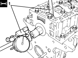
| Check one main journal at a time, without rotating the crankshaft. |
| Measurement | Value | Validity |
|---|---|---|
| Clearance between main bearings - crankshaft main journals (mm) | 0.025 ÷ 0.040 | 1.4 8v1.4 16v T-JET |
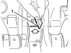
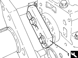
| Apply a 2-mm thick continuous sealant strip to the lower crankcase surface. |
| Measurement | Value | Validity |
|---|---|---|
| Piston outer diameter -Grade A (mm) | 71.960 ÷ 71.970 | 1.4 8v1.4 16v T-JET |
| Measurement | Value | Validity |
|---|---|---|
| Piston outer diameter - Grade B (mm) | 71.970 ÷ 71.980 | 1.4 8v1.4 16v T-JET |
| Measurement | Value | Validity |
|---|---|---|
| Piston outer diameter - Grade C (mm) | 71.980 ÷ 71.990 | 1.4 8v1.4 16v T-JET |
| Measure perpendicular to the gudgeon pin axis, 9 mm from the lower edge of the skirt. |
| Measurement | Value | Validity |
|---|---|---|
| Clearance between piston - cylinder liner (mm) | 0.030 ÷ 0.050 | 1.4 16v T-JET |
| Measurement | Value | Validity |
|---|---|---|
| Piston pin housing diameter (mm) | 17.978 ÷ 17.982 | 1.4 16v T-JET |
| Measurement | Value | Validity |
|---|---|---|
| Piston pin outer diameter (mm) | 17.970 ÷ 17.974 | 1.4 8v1.4 16v T-JET |
| Measurement | Value | Validity |
|---|---|---|
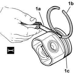
| Cylinder compression 1st sealing ring thickness (mm) | 1.170 ÷ 1.195 | 1.4 16v T-JET |
| Measurement | Value | Validity |
|---|---|---|
| Cylinder compression 2nd sealing ring thickness (mm) | 1.170 ÷ 1.190 | 1.4 16v T-JET |
| Measurement | Value | Validity |
|---|---|---|
| Cylinder compression 3rd sealing ring thickness (mm) | 1.970 ÷ 1.990 | 1.4 16v T-JET |
| Measurement | Value | Validity |
|---|---|---|
| Sealing ring oversize (mm) | 0.1 | 1.4 8v1.4 16v T-JET |
| Measurement | Value | Validity |
|---|---|---|
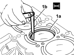
| Cylinder compression 1st sealing ring gap (mm) | 0.20 ÷ 0.35 | 1.4 16v T-JET |
| Measurement | Value | Validity |
|---|---|---|
| Cylinder compression 2nd sealing ring gap (mm) | 0.40 ÷ 0.60 | 1.4 16v T-JET |
| Measurement | Value | Validity |
|---|---|---|
| Cylinder compression 3rd sealing ring gap (mm) | 0.20 ÷ 0.40 | 1.4 16v T-JET |
| Measurement | Value | Validity |
|---|---|---|
| Sealing ring seat in piston - 1st groove (mm) | 1.220 ÷ 1.240 | 1.4 16v T-JET |
| Measurement | Value | Validity |
|---|---|---|
| Sealing ring seat in piston - 2nd groove (mm) | 1.210 ÷ 1.230 | 1.4 8v1.4 16v T-JET |
| Measurement | Value | Validity |
|---|---|---|
| Sealing ring seat in piston - 3rd groove (mm) | 2.010 ÷ 2.030 | 1.4 8v1.4 16v T-JET |
| Measurement | Value | Validity |
|---|---|---|
| Cylinder compression 1st sealing ring endfloat (mm) | 0.025 ÷ 0.070 | 1.4 16v T-JET |
| Measurement | Value | Validity |
|---|---|---|
| Cylinder compression 2nd sealing ring endfloat (mm) | 0.020 ÷ 0.060 | 1.4 16v T-JET |
| Measurement | Value | Validity |
|---|---|---|
| Cylinder compression 3rd sealing ring endfloat (mm) | 0.020 ÷ 0.060 | 1.4 16v T-JET |
| Measurement | Value | Validity |
|---|---|---|
| Big end diameter (mm) | 45.138 ÷ 45.148 | 1.4 16v T-JET |
| Measurement | Value | Validity |
|---|---|---|
| Small end diameter with bush (mm) | 17.993 ÷ 18.000 | 1.4 16v T-JET |
| The small end bush cannot be separated from the actual connecting rod.The bush is therefore handled by the Parts Dept. together with the connecting rod. |
| Tool | Description | Function | Validity |
|---|---|---|---|
| 1860815000 | Flange | Crankshaft rotation | 1.3 Multijet1.4 16v TJET |
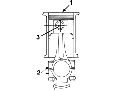
| The matching of the connecting rod-cap is the "BREAKING" type therefore the position is compulsory and the number corresponding to the position of the cylinder must be present. |
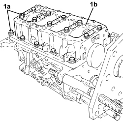
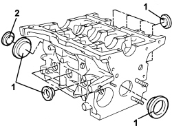
| Letters identifying the cylinder liner classes are shown on the crankcase. |
| Measurement | Value | Validity |
|---|---|---|
| Connecting rod half-bearing thickness (mm) | 1.544 ÷ 1.548 | 1.4 8v1.4 16v T-JET |
| Measurement | Value | Validity |
|---|---|---|
| Connecting rod half-bearing 1 oversize (mm) | 0.127 | 1.4 16v T-JET |
| Measurement | Value | Validity |
|---|---|---|
| Connecting rod half-bearing 2 oversize (mm) | 0.254 | 1.4 16v T-JET |
| Measurement | Value | Validity |
|---|---|---|
| Connecting rod half-bearing 3 oversize (mm) | 0.508 | 1.4 16v T-JET |
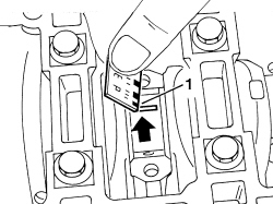
| The connecting rod caps are fracture type. If replaced, they are supplied pre-fractured by the manufacturer. Check that the parts are free of burrs, blisters, scratches or any other surface defect. Before installation, parts must be thoroughly washed, cleaned and dried. Fit the connecting rod caps so that the number stamped on each cap faces towards the same side as the number stamped on the big end. |
| Each connecting rod must be paired with its cap, respecting the numerical references stamped on the parts. Connecting rods and connecting rod caps are not interchangeable. |
| Component | Fastening | dia | Value (daNm) | Validity |
|---|---|---|---|---|
| Connecting rod caps | Bolt | M8 | 1.9 ÷ 2.1 + 40° ± 2° |
| Check one crankpin at a time, without rotating the crankshaft. |
| Measurement | Value | Validity |
|---|---|---|
| Clearance between connecting rod bearings - crankpin bearings (mm) | 0.024 ÷ 0.060 | 1.4 16v T-JET |
| Component | Fastening | dia | Value (daNm) | Validity |
|---|---|---|---|---|
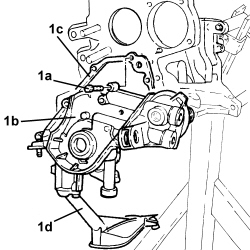
| Engine oil pump | Bolt | M6 | 0.9 ÷ 1.1 | 1.4 16v TJET |
| Component | Fastening | dia | Value (daNm) | Validity |
|---|---|---|---|---|
| Switch for engine oil pressure warning light | - | M14 | 2.9 ÷ 3.5 |
| Tool | Description | Function | Validity |
|---|---|---|---|
| 1860990000 | Fitting tool | Fitting crankshaft front cover oil sealFitting oil seal on exhaust camshaft | 1.4 8v1.4 16v TJET |
| Component | Fastening | dia | Value (daNm) | Validity |
|---|---|---|---|---|
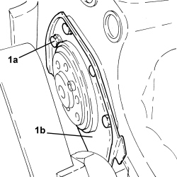
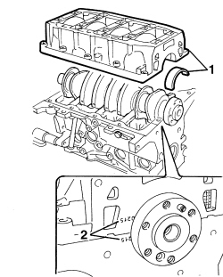
| Crankshaft to crankcase rear cover | Bolt | M6 | 0.8 ÷ 1.0 | 1.4 8v1.4 16v TJET |
| Tool | Description | Function | Validity |
|---|---|---|---|
| 2000004500 | Template | Crankshaft timing | 1.4 8v1.4 16v TJET |
| Component | Fastening | dia | Value (daNm) | Validity |
|---|---|---|---|---|
| Crankshaft gear | Bolt | M12 | 1.9 ÷ 2.1 + 107° + 113° | 1.4 16v TJET |
| Component | Fastening | dia | Value (daNm) | Validity |
|---|---|---|---|---|
| Rpm sensor | Bolt | M6 | 0.8 ÷ 1.0 | 1.4 8v1.4 16v TJET |
| Component | Fastening | dia | Value (daNm) | Validity |
|---|---|---|---|---|
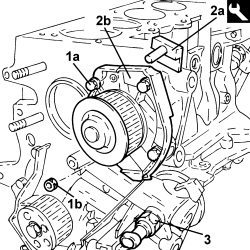
| Water pump | Bolt | M6 | 0.9 ÷ 1.1 | 1.4 16v TJET |
| Component | Fastening | dia | Value (daNm) | Validity |
|---|---|---|---|---|
| Water pump | Nut | M6 | 0.9 ÷ 1.1 | 1.4 16v TJET |
| When positioning the oil sump, avoid significant sideways movements that could remove the sealant. |
| Component | Fastening | dia | Value (daNm) | Validity |
|---|---|---|---|---|
| Engine oil sump | Bolt | M6 | 0.8 ÷ 1.0 | 1.4 16v TJET |
| Component | Fastening | dia | Value (daNm) | Validity |
|---|---|---|---|---|
| Engine oil sump | Nut | M6 | 0.8 ÷ 1.0 | 1.4 16v TJET |
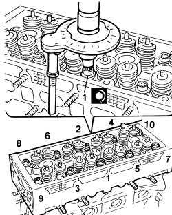
| Follow the order shown in the diagram for each tightening sequence. |
| Component | Fastening | dia | Value (daNm) | Validity |
|---|---|---|---|---|
| Cylinder head | Bolt | M9 | 3.0 + 90° + 90° | 1.4 16v TJET |
| Tool | Description | Function | Validity |
|---|---|---|---|
| 1860834000 | Spanner | Loosen/tighten the cylinder head extension bolts | 1.4 16v TJET |
| Component | Fastening | dia | Value (daNm) | Validity |
|---|---|---|---|---|
| Engine cylinder head extension | Bolt | M8 | 1.3 ÷ 1.6 | 1.4 16v TJET |
| Component | Fastening | dia | Value (daNm) | Validity |
|---|---|---|---|---|
| Engine cylinder head extension plugs | - | M16 | 1.3 ÷ 1.6 | 1.4 16v TJET |
| Tool | Description | Function | Validity |
|---|---|---|---|
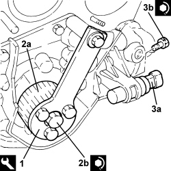
| 2000015800 | Counter-torque | Camshaft driven pulley lock | 1.4 16v TJET |
| Component | Fastening | dia | Value (daNm) | Validity |
|---|---|---|---|---|
| Driven timing pulley | Bolt | M12 | 10.8 ÷ 13.2 | 1.4 16v TJET |
| Component | Fastening | dia | Value (daNm) | Validity |
|---|---|---|---|---|
| Camshaft gears | Bolt | M12 | 12.0 | 1.4 16v TJET |
| Tool | Description | Function | Validity |
|---|---|---|---|
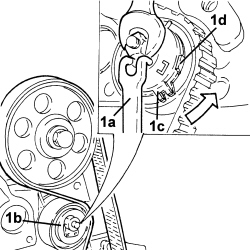
| 1860992000 | Bearings | Crankshaft timing | 1.4 16v TJET |
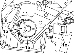
| Rotate the crankshaft proceeding gradually to prevent the tool pins being expelled by the compression of the pistons. |
| Tool | Description | Function | Validity |
|---|---|---|---|
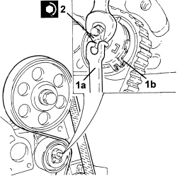
| 1860985000 | Locating pins | Camshaft timing | 1.4 16v TJET |
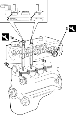
| Ensure that this operation is performed with the camshaft driven pulley slack. |
| Tool | Description | Function | Validity |
|---|---|---|---|
| 1860987000 | Spanner | Tensioning toothed timing drive belt | 1.4 8v1.4 16v TJET |
| Tool | Description | Function | Validity |
|---|---|---|---|
| 2000015800 | Counter-torque | Camshaft driven pulley lock | 1.4 16v TJET |
| Component | Fastening | dia | Value (daNm) | Validity |
|---|---|---|---|---|
| Driven timing pulley | Bolt | M12 | 10.8 ÷ 13.2 | 1.4 16v TJET |
| Component | Fastening | dia | Value (daNm) | Validity |
|---|---|---|---|---|
| Timing system moving tensioner | Nut | M8 | 2.2 ÷ 2.7 | 1.4 16v TJET |
| Component | Fastening | dia | Value (daNm) | Validity |
|---|---|---|---|---|
| Engine cylinder head extension plugs | - | M16 | 1.3 ÷ 1.6 | 1.4 16v TJET |
| Component | Fastening | dia | Value (daNm) | Validity |
|---|---|---|---|---|
| Water pump rigid inlet pipe | Bolt | M6 | 0.9 ÷ 1.1 | 1.4 16v TJET |
| Component | Fastening | dia | Value (daNm) | Validity |
|---|---|---|---|---|
| Ignition coils | Bolt | M6 | 0.8 ÷ 1.0 | 1.4 8v1.4 16v TJET |
| Component | Fastening | dia | Value (daNm) | Validity |
|---|---|---|---|---|
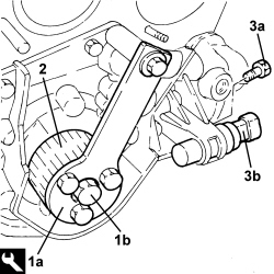
| Timing side power unit rigid support | Bolt | M10 | 5.4 ÷ 6.6 | 1.4 8v1.4 16v TJET |
| Component | Fastening | dia | Value (daNm) | Validity |
|---|---|---|---|---|
| Services pulley on crankshaft | Bolt | M8 | 2.3 ÷ 2.8 |
| Component | Fastening | dia | Value (daNm) | Validity |
|---|---|---|---|---|
| Heat exchanger and oil filter mounting - crankshaft front oil seal cover side | Connector | M20 | 4.1 ÷ 4.9 | 1.4 16v TJET |
| Component | Fastening | dia | Value (daNm) | Validity |
|---|---|---|---|---|
| Heat exchanger and oil filter mounting - engine block side | Bolt | M10 | 4.5 ÷ 5.5 | 1.4 16v TJET |
| Component | Fastening | dia | Value (daNm) | Validity |
|---|---|---|---|---|
| Exhaust manifold | Nut (to replace) | M8 | 1.4 ÷ 1.6 + 30° ± 3° | 1.4 16v TJET |
| Component | Fastening | dia | Value (daNm) | Validity |
|---|---|---|---|---|
| Exhaust manifold heat shield | Nut | M6 | 0.8 ÷ 1.0 | 1.4 16v TJET |
| The connectors should be tightened keeping the pipe still. Any movement of the pipe of more than 3° will adversely affect the seal of the connectors. |
| The connectors should be tightened keeping the pipe still. Any movement of the pipe of more than 3° will adversely affect the seal of the connectors. |
| Component | Fastening | dia | Value (daNm) | Validity |
|---|---|---|---|---|
| Turbocharger lubrication oil supply pipe - heat exchanger side | Connector | M6 | 0.8 ÷ 1.0 | 1.4 16v TJET |
| Component | Fastening | dia | Value (daNm) | Validity |
|---|---|---|---|---|
| Turbocharger lubrication oil supply pipe - turbocharger side | Connector | M12 | 1.8 ÷ 2.2 | 1.4 16v TJET |
| The connectors should be tightened keeping the pipe still. Any movement of the pipe of more than 3° will adversely affect the seal of the connectors. |
| The connectors should be tightened keeping the pipe still. Any movement of the pipe of more than 3° will adversely affect the seal of the connectors. |
| Component | Fastening | dia | Value (daNm) | Validity |
|---|---|---|---|---|
| Water supply pipe to engine oil heat exchanger | Connector | M16 | 3.0 ÷ 3.6 | 1.4 16v TJET |
| Tighten the "slotted bolt" first when connecting the pipe to the turbocharger. |
| The connectors should be tightened keeping the pipe still. Any movement of the pipe of more than 3° will adversely affect the seal of the connectors. |
| Component | Fastening | dia | Value (daNm) | Validity |
|---|---|---|---|---|
| Lubrication oil return pipe from turbocharger | Bolt | M6 | 0.8 ÷ 1.0 | 1.4 16v TJET |
| The connector should be tightened keeping the pipe still. Any movement of the pipe of more than 3° will adversely affect the seal of the connector. |
| Component | Fastening | dia | Value (daNm) | Validity |
|---|---|---|---|---|
| Turbocharger lubrication oil return pipe in sump - engine oil heat exchanger side | Connector | M16 | 3.0 ÷ 3.6 | 1.4 16v TJET |
| Component | Fastening | dia | Value (daNm) | Validity |
|---|---|---|---|---|
| Power steering support to engine | Bolt | M10 x 1.25 | 5.0 | 1.4 16v TJET |
| Component | Fastening | dia | Value (daNm) | Validity |
|---|---|---|---|---|
| Power steering pump to engine mounting | Bolt | M8 | 2.25 ÷ 2.75 |
| Component | Fastening | dia | Value (daNm) | Validity |
|---|---|---|---|---|
| Reinforcement strut to alternator mounting | Bolt | M8 | 2.25 ÷ 2.75 |
| Component | Fastening | dia | Value (daNm) | Validity |
|---|---|---|---|---|
| Power steering pump pulley | Bolt | M8 | 2.25 ÷ 2.75 |
| Component | Fastening | dia | Value (daNm) | Validity |
|---|---|---|---|---|
| Engine oil filter heat shield | Bolt | M6 | 0.8 ÷ 1.0 | 1.4 16v TJET |
| Component | Fastening | dia | Value (daNm) | Validity |
|---|---|---|---|---|
| Air chamber | Bolt (to be replaced) | M7 | 1.3 ÷ 1.7 | 1.4 16v TJET |
| Component | Fastening | dia | Value (daNm) | Validity |
|---|---|---|---|---|
| Intermediate driveshaft bearing support | Bolt | M8 | 2.3 ÷ 2.8 | 1.4 16v TJET |
| ... DATA ERROR - CROPPED TEXT | Ошибка данных - Текст обрезан ... |
|---|