500235 - 5580A85 RADAR UNIT for ADAPTIVE CRUISE CONTROL (A.C.C.) - Second level alignment with front bumper removed
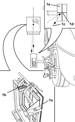
- Check the tyre inlation pressure and, if necessary, correct it.- Check that the tank is at least 50% full.- Check the vehicle geometry and, if necessary, correct it.- Check that the load carrying compartment is empty.- Check that the battery voltage is > 10.5 V.1. Position the vehicle in the specially designed calibration area as illustrated in the diagram below, trying to position it at right angles to the sliding guide (1a) for the radar mirror (1b) at a distance of 120 cm (± 5 cm), referring to the lines traced on the ground.| If the difference for the driving axis of the vehicle is > 5°, then alignment is impossible. |


| If the vehicle is fitted with polished alloy wheels, the rims must be protected in the areas where the rapid tightening clamps are fitted in order to prevent damage to the surface. It should be borne in mind that the protection fitted should be the same size in order not to affect the rapid tightening clamp support plane. |


| NEVER look directly at the laser source ! |
| If the laser reflection point does not appear on the projection surface, move the laser source until it is displayed. |


| If the laser beam does not pass through the slot in the diaphragm, adjust the height of the latter using the special screw. Carry out a further check, positioning the diaphragm by the axis for the centre line of the front wheel hub. Proceed as described until the laser radius passes through the slot in the diaphragm by both wheels (front and rear). |
| If, whilst adjusting the angle of the mirror in relation to the vertical axis, there is a non alignment in relation to the horizontal axis, correct this by regulating the horizontal adjustment screw as described previously. |


| For the correct positioning, fit the pre-alignment equipment until it is in contact with the outer edge of the radar. |

| NEVER look directly at the laser source ! |

| The road test should be carried out following the road traffic regulations in force. |

| The test should be carried out on a straight road or round bends of more than 500 m and the speed between vehicles A and B should not exceed 50 km/h. |
| The variation in the distance between the two vehicles is only noticed at an ambient temperature of > 3°C. If the ambient temperature is equal to 3°C the Adaptive Cruise Control is automatically positioned at the maximum distance. |