109484 - 2130B40 Gear selector SOLENOID VALVE UNIT - R.R.
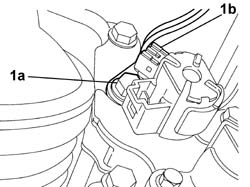
| Before proceed with the operation of removing the solenoid unit, position the gear lever in "N" |


| proceed carefully in order not to damage the electrical connection |


| Value - daNm | Fastening | Component | Ø | |
|---|---|---|---|---|
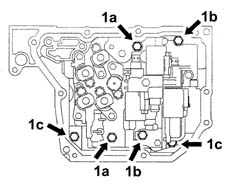
| 1a | 1 | Bolt | SOLENOID UNIT | M6 X 55 |
| Value - daNm | Fastening | Component | Ø | |
|---|---|---|---|---|
| 1b | 1 | Bolt | SOLENOID UNIT | M6 X 50 |
| Value - daNm | Fastening | Component | Ø | |
|---|---|---|---|---|
| 1c | 1 | Bolt | SOLENOID UNIT | M6 X 16 |
| Value - daNm | Fastening | Component | Ø | |
|---|---|---|---|---|
| 1c | 1 | Bolt | SOLENOID UNIT | M6 X 50 |

| Value - daNm | Fastening | Component | Ø | |
|---|---|---|---|---|
| 1c | 1 | Bolt | SOLENOID UNIT | M6 X 55 |

| Value - daNm | Fastening | Component | Ø | |
|---|---|---|---|---|
| 1a | 1.3 | Bolt | SOLENOID VALVE COVER FIXING, BOLT | M8 X 15 |
