177582 - 4410D10 Front suspension FRAME - R.R.


| Description | Code | Function | |
|---|---|---|---|
| 1c | Head extractor | 1.847.035.000 | Extracting steering rod pin from stub axle |


| Description | Connector | |
|---|---|---|
| 1a | Headlamp alignment corrector front potentiometer (CAF) | K001 |


| Description | Connector | |
|---|---|---|
| 1a | Servotronik solenoid valve | L070 |


| Description | Code | Function | |
|---|---|---|---|
| 2a | Crossmember | 1.870.595.000 | Power unit support |
| Description | Code | Function | |
|---|---|---|---|
| 2b | Support mountings | 1.870.650.000 | Power unit support |
| Description | Code | Function | |
|---|---|---|---|
| 3a | Crossmember | 1.860.851.003 | Power unit support |
| Description | Code | Function | |
|---|---|---|---|
| 3b | Vertical support | 1.870.748.000 | Power unit support |


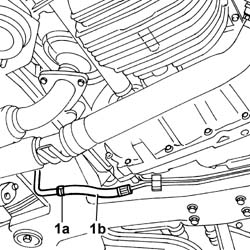
| Secure the pipe to the bodyshell, as best as possible, in order to prevent power assisted steering fluid leaks and to facilitate the subsequent operation of removing the frame. |


| Description | Code | Function | |
|---|---|---|---|
| 1a | Power unit support frame | 1.870.835.000 | Removing-refitting power unit |


| Value - daNm | Fastening | Component | Ø | |
|---|---|---|---|---|
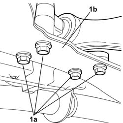
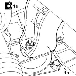
| 1a | 13 | Bolt | FRONT SUSPENSION SUBFRAME | M12 X 1.25 |

| Value - daNm | Fastening | Component | Ø | |
|---|---|---|---|---|
| 1a | 5 | Bolt | FRONT SUSPENSION SUBFRAME | M10 X 1.25 |
| Value - daNm | Fastening | Component | Ø | |
|---|---|---|---|---|
| 1b | 13 | Bolt | FRONT SUSPENSION SUBFRAME | M12 X 1.25 |

| Value - daNm | Fastening | Component | Ø | |
|---|---|---|---|---|
| 1a | (to the flexible mounting) 4 | Nut | RIGID REAR SUPPORT POWER UNIT | M10 |
| Value - daNm | Fastening | Component | Ø | |
|---|---|---|---|---|
| 1a | (Engine support) 4.5 | Nut | RIGID ENGINE MOUNT, TIMING SIDE | M10 X 1.25 |

| Value - daNm | Fastening | Component | Ø | |
|---|---|---|---|---|
| 1a | 0.5 | Bolt | PIPE BTWN PUMP + POWER STEERING BOX | M6 |
| Value - daNm | Fastening | Component | Ø | |
|---|---|---|---|---|
| 2 | 4 | Connector | PIPE BTWN PUMP + POWER STEERING BOX | M14 x1.5 |

| Value - daNm | Fastening | Component | Ø | |
|---|---|---|---|---|
| 1a | 4 | Connector | POWER STEERING PUMP SUPPLY PIPE | M18 X 1.5 |
| Value - daNm | Fastening | Component | Ø | |
|---|---|---|---|---|
| 1b | 4 | Connector | POWER ASSISTED STEERING PUMP/BOX PIPE | M16 X 1.5 |

| Description | Connector | |
|---|---|---|
| 1a | Servotronik solenoid valve | L070 |

| Value - daNm | Fastening | Component | Ø | |
|---|---|---|---|---|
| 1a | 2.8 | Nut | EXHAUST PIPE MOUNTS/FASTENERS | M8 |

| Description | Connector | |
|---|---|---|
| 1a | Headlamp alignment corrector front potentiometer (CAF) | K001 |

| Value - daNm | Fastening | Component | Ø | |
|---|---|---|---|---|
| 1a | 10 | Bolt | LOWER FRONT TRACK CONTROL ARMS | M12 x1.25 |

| Value - daNm | Fastening | Component | Ø | |
|---|---|---|---|---|
| 1a | 7.4 | Bolt | LOWER FRONT TRACK CONTROL ARMS | M10x.1.25 |

| Value - daNm | Fastening | Component | Ø | |
|---|---|---|---|---|
| 1b | 11.6 | Bolt | FRONT DAMPER FORK ON WISHBONE | M12 X 1.25 |
| Value - daNm | Fastening | Component | Ø | |
|---|---|---|---|---|
| 1d | 9 | Bolt | LOWER FRONT TRACK CONTROL ARMS | M12 X 1.25 |
| Value - daNm | Fastening | Component | Ø | |
|---|---|---|---|---|
| 2b | 5,5 | Nut | FRONT ANTI-ROLL BAR | M10 X 1.25 |
| Value - daNm | Fastening | Component | Ø | |
|---|---|---|---|---|
| 3b | 0.4 | Bolt | JOLTING SENSOR | M5 |

| Value - daNm | Fastening | Component | Ø | |
|---|---|---|---|---|
| . | 4.5 | Nut | ADJUSTABLE LINK BALL JOINTS | M10 x 1.25 |
| Value - daNm | Fastening | Component | Ø | |
|---|---|---|---|---|
| . | 7 | Nut | FRONT HUBS COMPLETE WITH BEARING | M24 |
| Description | Code | Function | |
|---|---|---|---|
| 1b | Torque wrench | 1.820.622.000 | - |
| Value - daNm | Fastening | Component | Ø | |
|---|---|---|---|---|
| 1a | 0.5 | Nut | AIR CLEANER CASE MOUNT | M6 |


| Value - daNm | Fastening | Component | Ø | |
|---|---|---|---|---|
| 2a | 0.5 | Nut | COOLANT RADIATOR SUPPORT BEAM | M6 |

| Value - daNm | Fastening | Component | Ø | |
|---|---|---|---|---|
| 2 | Bolt | STEERING SHAFT MOUNTING | M8 |