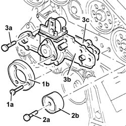
505999 - 1088C20 Water pump - R.R. with engine removed

Removing ( Refitting ) 1. Undo the bolts (1a) and remove the timing belt guards (1b).
1. Loosen the timing belt tensioner bolts.2. Release the timing drive belt from the camshaft drive pullies.
1. Undo the bolts (1a) and remove the water pump drive pulley (1b).2. Undo the bolt (2a) and remove the timing belt fixed tensioner (2b).3. Undo the bolts (3a) and remove the water pump (3b) complete with gasket (3c).
Refitting ( Removing ) - Fit the water pump with a new gasket and secure it to the crankcase tightening the bolts to torque C.
Value - daNmFasteningComponentØ  
.0.8 - 1.2-WATER PUMPM6
- Fit the fixed belt tensioner for the timing belt and fasten it using the bolt.- Fit the water pump drive pulley and secure it using the bolts.
Value - daNmFasteningComponentØ  
.0,8 - 1,2-ENGINE OIL PUMP DRIVE PULLYM6
- Engine tuning.1. Fit tool A in place of the camshaft caps removed.
DescriptionCodeFunction
.Template Kit1.860.820.000Timing
1. Position the template for the right inlet cylinder no. 1 1.860.820.0012. Position the template for the right exhaust cylinder no. 1 1.825.040.0023. Position the template for the left exhaust cylinder no. 4 1.825.040.0034. Position the template for the left inlet cylinder no. 6 1.860.820.002
- Loosen the bolts for the camshaft drive pullies using the special tool for counter-torque.
DescriptionCodeFunction
.Support for counter-torque1.860.831.000-
- Fit the timing belt drive pulley.1. Fit the tool A (1a) complete with dial gauge (1b) in the seat for the spark plug for cylinder no. 1.
DescriptionCodeFunction
1a Extension1.860.895.000-
- Rotate the crankshaft through small rotations (in both directions) until the piston for the right head timing side cylinder no. 1 is at T.D.C. in the explosion stroke.
Take care that the last rotation of the crankshaft is in the direction of rotation of the engine.
1. Fit the timing drive belt starting from the drive pulley and continuing in an anti-clockwise direction making sure that the drive branches are properly taut.
1. Fit the tool (1a) and secure it using bolt (1b) for the alternator and bolt (1c) for the water pump.
A suitable spacer should be fitted on the bolt (1b) to regain the size of the alternator.
The tooth (1d) for the tool should engage with the moving part of the timing belt tensioner.
DescriptionCodeFunction
1a Belt tensioner1.860.950.000-
2. Act on the belt tensioner tool nut (2a) until the moving reference for the belt tensioner (2b) is under the fixed reference.
1. Tighten the bolts (1a) for the camshaft drive pullies to torque C using tools (1b) A for counter-torque.
Value - daNmFasteningComponentØ  
1a 7.3 - 10.6-CAMSHAFT DRIVE PULLIESM10
DescriptionCodeFunction
1b Support for counter-torque1.860.831.000-
- Remove the tool A.
DescriptionCodeFunction
.Template Kit1.860.820.000-
- Fit the camshaft caps in place of the tool removed and secure them by tightening the bolts to torque C.
Value - daNmFasteningComponentØ  
.1.8 - 2.5BoltCAMSHAFT CAPSM8
- Rotate the crankshaft through two revolutions in its direction of rotation to allow the timing belt to bed in.1. Check that the moving reference for the timing belt tensioner coincides with the fixed reference.2. If the references are not aligned, gently release the tensioner tension acting on the nut for the tensioning tool until the reference coincide.3. Tighten the bolts for the timing belt tensioner to torque C.
Value - daNmFasteningComponentØ  
3 2.4 - 3.2BoltTIMING BELT TENSIONERM8
- Remove the tool A.
DescriptionCodeFunction
.Belt tensioner1.860.950.000-
1. Fit the tool A.
DescriptionCodeFunction
1 Counter-torque1.860.779.000-
2. Fit the engine components single belt pulley (2a) and secure it tightening the nuts (2b) to torque C.
Value - daNmFasteningComponentØ  
2d 23.2 ÷ 31.2NutSINGLE ENGINE COMPONENTS DRIVE BELT PULLEYM28
- Remove the tool A.
DescriptionCodeFunction
.Counter-torque1.860.779.000-
- Fit the tappet covers and secure them using the bolts.- Fit the ignition coils and secure them using the bolts.- Fit the protective timing cover mounting bracket and secure it using the bolts.- Fit the timing belt guards and secure them using the bolts.- Place the electrical wiring in position and fasten it to the bands.- Connect the electrical connections to the ignition coils.- Connect the electrical connections to the injectors.- Fit the electrical wiring mounting brackets to the tappet covers and secure them using the bolts.- Connect the electrical connection for the front detonation sensor.- Fit the ignition coil cover for the left cylinder head and secure it using the bolts.- Connect the earth lead to the left cylinder head tappet cover.- Connect the electrical connection to the engine coolant temperature sensor.- Connect the electrical connection for the rear detonation sensor.- Connect the electrical connection for the engine rpm and timing sensor.- Connect the electrical connection for the cam angle sensor.- Fit the intake chamber assembly and secure it using the bolts.- Tighten the bands securing the air intake manifolds to the intake chamber.- Connect the engine oil vapour recovery pipe.- Connect the electrical connection for the throttle casing.- Connect the earth lead to the left cylinder head tappet cover.