75040 - 1056B90 SYSTEM CABLE LOOM - R.R.
| Description | Connector | |
|---|---|---|
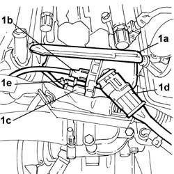
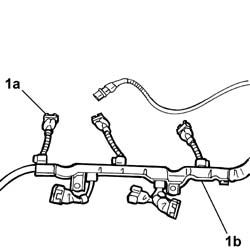
| 1a | Engine management control unit | M010A |
| Description | Connector | |
|---|---|---|
| 1a | Engine management control unit | M010B |

| Description | Connector | |
|---|---|---|
| 1b | Earth on engine | C040 |

| Description | Connector | |
|---|---|---|
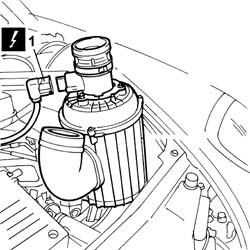
| 1 | Integrated throttle casing actuator | N075 |

| Description | Connector | |
|---|---|---|
| 1a | Lambda sensor on catalyzer | K017 |
| Description | Connector | |
|---|---|---|
| 1a | Lambda sensor on catalyzer 2 | K018 |
| Description | Connector | |
|---|---|---|
| 1b | Detonation sensor - 2 | K050 |
| Description | Connector | |
|---|---|---|
| 1c | Air conditioning-heater front coupling | D008A |

| Description | Connector | |
|---|---|---|
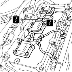
| 1 | Ignition coil | A030A |
| Description | Connector | |
|---|---|---|
| 1 | Ignition coil | A030B |
| Description | Connector | |
|---|---|---|
| 1 | Ignition coil | A030C |
| Description | Connector | |
|---|---|---|
| 1 | Ignition coil | A030D |
| Description | Connector | |
|---|---|---|
| 1 | Ignition coil | A030E |
| Description | Connector | |
|---|---|---|
| 1 | Ignition coil | A030F |
| Description | Connector | |
|---|---|---|
| 2 | Injector | N070A |
| Description | Connector | |
|---|---|---|
| 2 | Injector | N070B |
| Description | Connector | |
|---|---|---|
| 2 | Injector | N070C |
| Description | Connector | |
|---|---|---|
| 2 | Injector | N070D |
| Description | Connector | |
|---|---|---|
| 2 | Injector | N070E |
| Description | Connector | |
|---|---|---|
| 2 | Injector | N070F |
| Description | Connector | |
|---|---|---|
| 1 | Earth on engine | C040 |

| Description | Connector | |
|---|---|---|
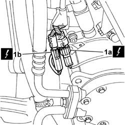
| 1b | Lambda sensor on pre-catalyzer | K015 |
| Description | Connector | |
|---|---|---|
| 1c | Lambda sensor on pre-catalyzer -2 | K016 |
| Description | Connector | |
|---|---|---|
| 1d | Detonation sensor - 2 | K051 |
| Description | Connector | |
|---|---|---|
| 1a | I.E. engine temperature sensor | K045 |


| Description | Connector | |
|---|---|---|
| 1 | Alternator | A010A |
| Description | Connector | |
|---|---|---|
| 1 | Alternator | A010B |

| Description | Connector | |
|---|---|---|
| 1b | Starter motor | A020A |
| Description | Connector | |
|---|---|---|
| 1b | Starter motor | A020B |

| Description | Connector | |
|---|---|---|
| 1a | Air conditioning compressor engagement electro-magnet | L020 |
| Description | Connector | |
|---|---|---|
| 1b | Engine oil level sensor | K032 |
| Description | Connector | |
|---|---|---|
| 1a | Lambda sensor on pre-catalyzer -2 | K016 |

| Description | Connector | |
|---|---|---|
| . | Air conditioning compressor engagement electro-magnet | L020 |
| Description | Connector | |
|---|---|---|
| . | Engine oil level sensor | K032 |
| Description | Connector | |
|---|---|---|
| . | Starter motor | A020A |
| Value - daNm | Fastening | Component | Ø | |
|---|---|---|---|---|
| 0.5 | Nut | STARTER MOTOR | M8 |
| Description | Connector | |
|---|---|---|
| . | Starter motor | A020B |
| Description | Connector | |
|---|---|---|
| . | Alternator | A010A |
| Value - daNm | Fastening | Component | Ø | |
|---|---|---|---|---|
| 0.5 | Nut | ALTERNATOR | M8 |
| Description | Connector | |
|---|---|---|
| . | Alternator | A010B |
| Description | Connector | |
|---|---|---|
| 1 | I.E. engine temperature sensor | K045 |
| Description | Connector | |
|---|---|---|
| . | Lambda sensor on pre-catalyzer | K015 |
| Description | Connector | |
|---|---|---|
| . | Lambda sensor on pre-catalyzer -2 | K016 |
| Description | Connector | |
|---|---|---|
| . | Detonation sensor - 2 | K051 |
| Description | Connector | |
|---|---|---|
| Ignition coil | A030A |
| Description | Connector | |
|---|---|---|
| . | Ignition coil | A030B |
| Description | Connector | |
|---|---|---|
| . | Ignition coil | A030C |
| Description | Connector | |
|---|---|---|
| . | Ignition coil | A030D |
| Description | Connector | |
|---|---|---|
| . | Ignition coil | A030E |
| Description | Connector | |
|---|---|---|
| . | Ignition coil | A030F |
| Description | Connector | |
|---|---|---|
| Injector | N070A |
| Description | Connector | |
|---|---|---|
| 2 | Injector | N070B |
| Description | Connector | |
|---|---|---|
| 2 | Injector | N070C |
| Description | Connector | |
|---|---|---|
| 2 | Injector | N070D |
| Description | Connector | |
|---|---|---|
| 2 | Injector | N070E |
| Description | Connector | |
|---|---|---|
| 2 | Injector | N070F |
| Description | Connector | |
|---|---|---|
| . | Lambda sensor on catalyzer | K017 |
| Description | Connector | |
|---|---|---|
| . | Lambda sensor on catalyzer 2 | K018 |
| Description | Connector | |
|---|---|---|
| . | Detonation sensor - 2 | K050 |
| Description | Connector | |
|---|---|---|
| . | Air conditioning-heater front coupling | D008A |
| Description | Connector | |
|---|---|---|
| . | Integrated throttle casing actuator | N075 |
| Description | Connector | |
|---|---|---|
| Engine management control unit | M010A |
| Description | Connector | |
|---|---|---|
| . | Engine management control unit | M010B |