752225 - 1024A10 CRANKSHAFT - R.R. with engine removed - Check and, if necessary, replace crankshaft bearings and crankpins
| Description | Connector | |
|---|---|---|
| 2 | Integrated throttle casing actuator | N075 |


| Description | Connector | |
|---|---|---|
| 1 | Timing sensor | K047 |
| Description | Connector | |
|---|---|---|
| 2 | Rpm sensor | K046 |
| Description | Connector | |
|---|---|---|
| 3 | Detonation sensor - 2 | K050 |
| Description | Connector | |
|---|---|---|
| 4 | I.E. engine temperature sensor | K045 |


| Description | Connector | |
|---|---|---|
| 1 | Detonation sensor - 2 | K051 |
| Description | Connector | |
|---|---|---|
| 3 | Injector | N070A |
| Description | Connector | |
|---|---|---|
| . | Injector | N070B |
| Description | Connector | |
|---|---|---|
| . | Injector | N070C |
| Description | Connector | |
|---|---|---|
| . | Injector | N070D |
| Description | Connector | |
|---|---|---|
| . | Injector | N070E |
| Description | Connector | |
|---|---|---|
| . | Injector | N070F |
| Description | Connector | |
|---|---|---|
| 4 | Ignition coil | A030A |
| Description | Connector | |
|---|---|---|
| . | Ignition coil | A030B |
| Description | Connector | |
|---|---|---|
| . | Ignition coil | A030C |
| Description | Connector | |
|---|---|---|
| . | Ignition coil | A030D |
| Description | Connector | |
|---|---|---|
| . | Ignition coil | A030E |
| Description | Connector | |
|---|---|---|
| . | Ignition coil | A030F |


| Description | Connector | |
|---|---|---|
| 1b | Ignition coil | A030A |
| Description | Connector | |
|---|---|---|
| . | Ignition coil | A030B |
| Description | Connector | |
|---|---|---|
| . | Ignition coil | A030C |
| Description | Connector | |
|---|---|---|
| . | Ignition coil | A030D |
| Description | Connector | |
|---|---|---|
| . | Ignition coil | A030E |
| Description | Connector | |
|---|---|---|
| . | Ignition coil | A030F |


| Description | Code | Function | |
|---|---|---|---|
| 1 | Counter-torque | 1.860.779.000 | - |
| To release the crankcase sump, tap it gently using a wooden or resin hammer, then use a screwdriver for leverage in the projections at the sides of the sump. |

| Description | Code | Function | |
|---|---|---|---|
| 2 | Extractor | 1.860.954.001 | Tool for extracting chain from engine oil pump |


| Description | Code | Function | |
|---|---|---|---|
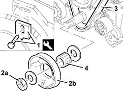
| 1 | Counter-torque | 1.860.779.000 | - |
| Description | Code | Function | |
|---|---|---|---|
| . | Counter-torque | 1.860.779.000 | - |

| Description | Code | Function | |
|---|---|---|---|
| 1 | Flange | 1.860.815.000 | - |
| Description | Code | Function | |
|---|---|---|---|
| . | Flange | 1.860.815.000 | - |


| Description | Code | Function | |
|---|---|---|---|
| 1c | Mallet | 1.846.011.000 | - |
| Description | Code | Function | |
|---|---|---|---|
| 1d | Extractor | 1.860.953.000 | - |
| Description | Code | Function | |
|---|---|---|---|
| 1e | Extractor | 1.860.782.000 | - |

| Subject | Value | |
|---|---|---|
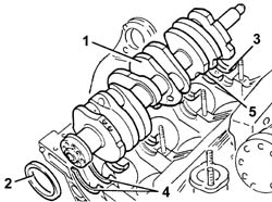
| . | Crankshaft bearings | - |
| - | CL thickness A | 1.833 - 1.839 |
| - | CL. B | 1.839 - 1.845 |
| - | CL. C | 1.845 - 1.851 |
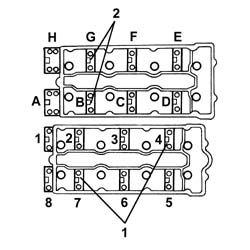
| T he thrust washer lubrication ducts should be facing the crankshaft thrust washers. |
| The bearing caps are numbered from 1 to 4 starting from the front of the engine |
| Value - daNm | Fastening | Component | Ø | |
|---|---|---|---|---|
| . | (Engine crankcase side) 2.5 + 79° | Nuts in oil | MAIN BEARING CAPS | M12 |
| Value - daNm | Fastening | Component | Ø | |
|---|---|---|---|---|
| . | 2.4 - 2.6 + 77° - 81° (Engine crankcase side) | Nut | MAIN BEARING CAPS | M12 |
| Description | Code | Function | |
|---|---|---|---|
| . | Torque wrench | 1.860.942.000 | Angular tightening of bearing cap bolts |
| The oil seal should be fitted in the housing so that it covers the small openings (1c). |
| Description | Code | Function | |
|---|---|---|---|
| 1b | Fitting tool | 1.860.794.000 | - |

| Description | Qty. | Component | Type | Classification | |
|---|---|---|---|---|---|
| 1a | Dow corning 7091 | - | ENGINE REAR MOUNT GASKETS | Silicone sealant | - |
| The oil sump should be fitted within 15 minutes of applying the sealant in the openings for sealing the crankshaft rear support. |
| If this is not the case, remove the excess sealant. |

| Description | Code | Function | |
|---|---|---|---|
| . | Flange | 1.860.815.000 | - |
| The connecting rod caps have the number of the cylinder to which they belong on the side: when refitting, this number should be on the usual side on the big end. |
| Value - daNm | Fastening | Component | Ø | |
|---|---|---|---|---|
| . | 5.4 - 6.0 | Nut | CONNECTING ROD CAPS | M9 |
| Value - daNm | Fastening | Component | Ø | |
|---|---|---|---|---|
| . | 2.1 + 48° ÷ 52° | Bolt | CONNECTING ROD CAPS | M9 |
| Description | Code | Function | |
|---|---|---|---|
| . | Torque wrench | 1.860.942.000 | Angular tightening of bearing cap bolts |
| Description | Code | Function | |
|---|---|---|---|
| . | Flange | 1.860.815.000 | Crankshaft rotation |
| Description | Code | Function | |
|---|---|---|---|
| 2 | Counter-torque | 1.860.779.000 | - |
| Value - daNm | Fastening | Component | Ø | |
|---|---|---|---|---|
| . | 3.0 + 50° | - | ENGINE FLYWHEEL | M10 |
| Description | Code | Function | |
|---|---|---|---|
| . | Counter-torque | 1.860.779.000 | - |

| Value - daNm | Fastening | Component | Ø | |
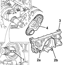
|---|---|---|---|---|
| . | 8.0 - 9.7 | Bolt | Engine oil pump drive chain | M14 |
| Description | Qty. | Component | Type | Classification | |
|---|---|---|---|---|---|
| . | Dow corning, 7091 | - | OIL SUMP | Silicone sealant |
| Value - daNm | Fastening | Component | Ø | |
|---|---|---|---|---|
| . | 1.4 - 2.0 | Bolt | CRANKCASE SUMP | M7 |
| Description | Code | Function | |
|---|---|---|---|
| . | Template Kit | 1.860.820.000 | Timing |

| Description | Code | Function | |
|---|---|---|---|
| . | Support for counter-torque | 1.860.831.000 | Loosen/tighten driven toothed pulley bolt |
| Description | Code | Function | |
|---|---|---|---|
| 1a | Extension | 1.860.895.000 | T.D.C. check |
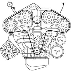
| Take care that the last rotation of the crankshaft is in the direction of rotation of the engine. |

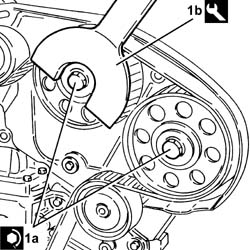
| A suitable spacer should be fitted on the bolt (1b) to regain the size of the alternator. |
| The tooth (1d) for the tool should engage with the moving part of the timing belt tensioner. |
| Description | Code | Function | |
|---|---|---|---|
| 1a | Belt tensioner | 1.860.950.000 | Timing belt tensioning |

| Value - daNm | Fastening | Component | Ø | |
|---|---|---|---|---|
| 1a | 7.3 - 10.6 | - | CAMSHAFT DRIVE PULLIES | M10 |
| Description | Code | Function | |
|---|---|---|---|
| 1b | Support for counter-torque | 1.860.831.000 | Loosen/tighten driven toothed pulley bolt |
| Description | Code | Function | |
|---|---|---|---|
| . | Template Kit | 1.860.820.000 | Engine tuning |
| Value - daNm | Fastening | Component | Ø | |
|---|---|---|---|---|
| . | 1.8 - 2.5 | Bolt | CAMSHAFT CAPS | M8 |
| Value - daNm | Fastening | Component | Ø | |
|---|---|---|---|---|
| 3 | 2.4 - 3.2 | Bolt | TIMING BELT TENSIONER | M8 |

| Description | Code | Function | |
|---|---|---|---|
| . | Belt tensioner | 1.860.950.000 | Timing belt tensioning |
| Description | Code | Function | |
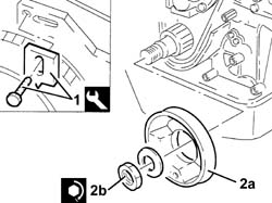
|---|---|---|---|
| 1 | Counter-torque | 1.860.779.000 | - |
| Value - daNm | Fastening | Component | Ø | |
|---|---|---|---|---|
| 2b | 23.2 ÷ 31.2 | Nut | SINGLE ENGINE COMPONENTS DRIVE BELT PULLEY | M28 |
| Description | Code | Function | |
|---|---|---|---|
| . | Counter-torque | 1.860.779.000 | - |