78454 - 2710A10 DRIVE SHAFT with joints (one), left or right - R.R.

Removing ( Refitting ) - Position the vehicle on a lift.    See in Op. 4450B04 Right FRONT WHEEL (one) - R.R.- Raise the lift.    See in Op. 7055B42 FRONT WHEEL ARCH LINER (one), left or right - R.R.    See in Op. 7055B64 Engine compartment DUST SEAL in front wheel arch (one), left or right - R.R.1. Using a hammer and chisel, remove the staking from the nut fixing the wheel hub and then undo it.
1. Disconnect the right driveshaft band fixing it to the intermediate driveshaft.
1. Undo the fixing bolts.2. Undo the fixing nut (2a) and disconnect the end of the anti-roll bar (2b).3. Undo the fixing nut (3a) and move the accelerator sensor (3b) aside.
1. Undo the fixing bolts.2. Separate the two heads from the suspension housing.3. Remove the suspension fork.4. Move the steering knuckle back and release the driveshaft three-lobe joint from the housing in the intermediate shaft, then remove the right driveshaft.
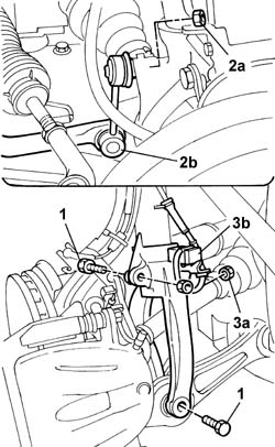
Take great care not to damage the brake fluid pipes and the electrical leads for the sensors, if necessary, release them from the bands on the steering knuckle.
Refitting ( Removing ) - Check that the driveshaft is intact.- Check that the boots are not damaged and that they contain the lubricating grease.- The boot must be replaced if it shows signs of wear.
If the grease has to be replaced, use TUTELA MRM ZERO introducing equal amounts (about 70gr) into both the boot and the intermediate driveshaft joint.
DescriptionQty.ComponentTypeClassification
.TUTELA MRM ZERO140 ± 10DRIVESHAFT CONSTANT VELOCITY JOINTSGrease
- Fit the driveshaft in the housing on the intermediate driveshaft.- Fit the suspension fork on the shock absorber.- Return the steering knuckle to its original position checking that the driveshaft is fitted in the housing on the intermediate driveshaft.- Secure the ends in the special housings in the suspension and tighten the fixing bolts to torque.
Value - daNmFasteningComponentØ  
.3.4BoltFRONT SHOCK ABSORBERS (S.M.)M8
- Tighten the bolts fixing the forks to torque.
Value - daNmFasteningComponentØ  
.9BoltFRONT DAMPER FORK ON WISHBONEM12
Value - daNmFasteningComponentØ  
.11.6BoltFRONT DAMPER FORK ON WISHBONEM12 X 1.25
- Tighten the nuts fixing the anti-roll bar track rod ends to torque.
Value - daNmFasteningComponentØ  
.5.5NutFRONT ANTI-ROLL BAR JOINTSM10 X 1.25
- Fit the acceleration sensor in the housing on the fork and secure it using the nut.- Secure the driveshaft to the intermediate driveshaft using new bands.- Tighten the wheel hub fixing nut to torque.
Value - daNmFasteningComponentØ  
.7+ 55°NutFRONT HUBS COMPLETE WITH BEARINGM22
1. Proceed with staking the nut following the illustration below.
    See in Op. 7055B64 Engine compartment DUST SEAL in front wheel arch (one), left or right - R.R.    See in Op. 7055B42 FRONT WHEEL ARCH LINER (one), left or right - R.R.- Lower the lift.    See in Op. 4450B04 Right FRONT WHEEL (one) - R.R.- Remove the vehicle from the lift.