162340 - COMPOSITION OF THE SYSTEM
DIAGRAM
The composition of the automatic climate control system is illustrated in the diagram below: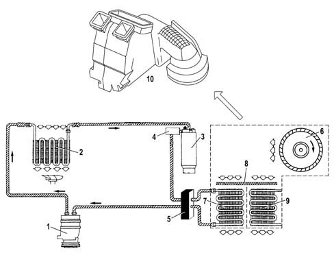
- High Pressure circuit, comprising the section of the system including the compressor, the condenser, the drier filter and the expansion valve. The pressure values in this circuit vary between 10 and 17 bar (80-100°C).
- Low Pressure Circuit, comprising the section of the system incuding the expansion valve and the evaporator. The pressure values in this circuit vary between 0.5 and 2 bar (1-5°C).
DESCRIPTION OF THE COMPONENTS
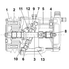
1. Compressor
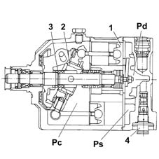
This is the operating machine for the climate control system that uses the mechanical energy fro the engine via a pulley and the electro-magnetic clutch to circulate the coolant fluid in the circuit.Depending on the version, this vehicle is equipped with either SANDEN or NIPPODENSO variable capacity compressors. These compressors make it possible to gradually alter the flow rate of the coolant fluid reaching the evaporator.The adoption of these compressors makes the presence of the frost sensor redundant and it is therefore no longer fitted.The adjustment of these compressors is based on the intake pressure value according to the following logic:- low pressure, the capacity of the compressor tends towards the minimum value.
- High pressure, the capacity increases.
- "low intake pressure" means that he load on the climate control system is such that it does not require a high fluid flow rate. Therefore the intake pressure for the compressor is reduced compared with normal operation and the capacity of the compressor is reduced.
- "high intake pressure" means that there is an increased load on the climate control system and the amount of coolant fluid required is high. Therefore the pressure at the compressor intake is increased compared with normal operation and the capacity of the compressor increases to increase the flow rate of the fluid in the circuit.
- direction of rotation: clockwise
- Max continuous number of revs: 8500 rpm.
- Max non-continuous number of revs: 9200 rpm.
- Number of pistons: 7.
- Min stroke: 4.5 mm.
- Max stroke: 28.69 mm.
- Min capacity: 8 cm³/rev
- Max capacity: 161 cm³/rev
- Quantity of lubricant: 140 ± 10 cm³ .
- Type of oil: ND 8.
- direction of rotation: clockwise.
- Max continuous number of revs: 7000 rpm.
- Max non-continuous number of revs: 8000 rpm.
- Number of pistons: 7.
- Min stroke: 2.2 mm.
- Max stroke: 34.2 mm.
- Min capacity: 10.4 cm³/rev
- Max capacity: 161.3 cm³/rev
- Quantity of lubricant: 135 cm³.
- Type of oil: ND 8.
2. Condenser
The condenser is a heat exchanger located in front of the engine cooling radiator and therefore air comes into contact with it whilst the vehicle is moving forward.The condenser is positioned between the compressor outlet and the inlet for the drier filter and has the function of liquifying the refrigerant in a gaseous state coming from the compressor: The refrigerant fluid in a gaseous state and at a high temperature passes throug the condenser coils and liquifies, on average, at a temperature of 60°C.When the vehicle is stationary or driving in traffic, the air is moved by the engine cooling circuit radiator fan.An insufficient thermal exchange in the condenser causes the incomplete condensation of the fluid and, therefore, an increase in the system pressure, considerably reducing the efficiency of the actual system.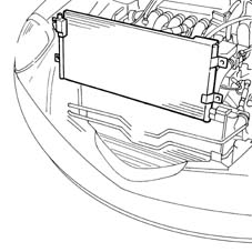
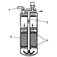
3. Drier filter
The drier filter is connected to the condenser outlet and the inlet for the evaporator and has the following functions: filtering any impurities in the refrigerant fluid (containing some of the compressor oil), separating the fluid from possible dampness, acting as a reserve reservoir for the actual refrigerant.The impurities that could block the expansion valve are trapped by two filtering layers. The possible dampness is absorbed by a chemical compound known as silicagel.The refrigerant fluid enters through the intake (1) in a liquid state (coming from the condenser), passes through the first of the two filtering layers (3), which traps any impurities, is filtered by the silicagel (4), which retains the dampness and then, lastly, passes through the second filtering layer.The fluid comes out of the filter through the outlet pipe (2) and flows to the expansion valve. The intake for the pipe (2) is positioned at the base of the filter to guarantee that the refrigerant fluid sent to the expansion valve is in a liquid state. In effect, it can happen that there are some saturated vapours at the filter inlet (condenser outlet). In this case, the refrigerant fluid in a gaseous state remains in the top part of the filter. The introduction of refrigerant fluid in a gaseous state into the evaporator (via the expansion valve) will reduce the efficiency of the system.A certain amount of compressor lubircation oil, which normally circulates mixed with the refrigerant fluid, is also deposited at the bottom of the filter. The outlet pipe also draws in lubrication oil in addition to refrigerant fluid in a liquid state.The level of the fluid inside the drier filter mainly depends on the temperature of the actual fluid and the system load conditions.| the filter must be kept with the connectors sealed in a dry environment until the moment it is fitted in order to prevent dampness from entering. |
4. Multi-stage pressure switch (4 STAGE)
Located on the high pressure inlet pipe on the drier filter.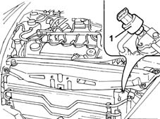
- 1st stage (about 2.5 bar): minimum pressure that the compressor can be switched on at.
- 2nd stage (about 15 bar): pressure that requires the engagement of the first fan speed.
- 3rd stage (about 20 bar): pressure that requires the engagement of the second fan speed.
- 4th stage (about 28 bar): maxmum pressure that switches off the compressor.
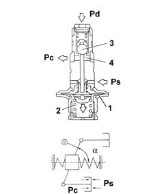
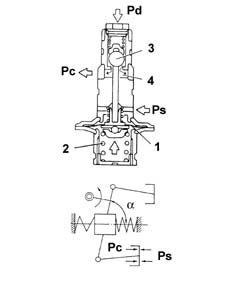
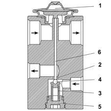
5. Expansion valve
The expansion valve is fitted on the evaporator inlet and outlet ducts with the task of regulating the flow and expansion of the R134a fluid at the evaporator intake.The refrigerant fluid undergoes a sudden and drastic fall in pressure and temperature inside the valve. This results from the fluid entering being made to pass through an opening at high pressure (10 - 17 bar). The section of the opening is determined by the position of the shutter (4), which is automatically modified by the actual valve.The automatic adjustment of the section through which the refrigerant fluid passes, inside the expansion valve, is carried out by a sensitive bulb (1) which is affected by the pressure of the refrigerant fluid coming out of the evaporator. Depending on the latter, the valve suitably regulates the narrow section (2) acting, by means of a rod (6), on the shutter, opposed by a spring (3) and determines the extent of the refrigerant fluid flow. The opposing spring is pre-loaded via a regulation screw (5) in production.The valve regulation logic is as follows:- the increase in pressure at the evaporator outlet, detected by the bulb, ensures that the valve tends to close with a consequent decrease in the flow rate of the fluid in the evaporator.
- A low evaporator outlet pressure involves an increase in the narrow section and, therefore, the flow of refrigerant fluid.
| The valve regulation screw is calibrated during production and should NOT be tampered with to avoid adversely affecting the efficiency of the system. |
6. Fan
| ... DATA ERROR - CROPPED TEXT | Ошибка данных - Текст обрезан ... |
|---|