162345 - DESCRIPTION OF THE WEBASTO SYSTEM
USAGE
The additional heater is optional on all versions of this vehicle.It is the Webasto Thermo Top C. modelThis device makes it possible to:- pre-heat the engine coolant
- reduce the time the engine takes to warm up
- heat the passenger compartment
- less engine wear
- a reduction in harmful emissions
- improved comfort
- increased safety
DESCRIPTION OF THE SYSTEM
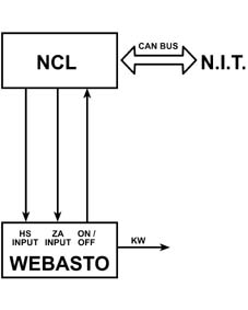
The system is illustrated in the diagram below:
- interface with the engine cooling system: the coolant leaving the power unit is directed to the heater and is returned to the circuit by a dedicated electric pump.
- Interface with the fuel supply system: The heater burner is supplied with fuel, taken directly from the tank (9) by means of an electric pump and conveyed in a special pipe (5).
- Interface with the electrical system: the heater is fitted with dedicated connectors which ensure the supply for the two electric pumps (fuel and coolant), the burner heater plug, the management control unit and the interconnection with the NCL.
DESCRIPTION OF THE MAIN COMPONENTS
Heater
The heater is the central unit of the system. It ensures the heating of the engine fluid and the management of the system operating parameters.
- a combustion control sensor, measuring the temperature of the actual combustion. According to the value recorded, the control unit varies the speed (flow rate) of the air intake fan, in order to ensure the optimum stoichiometric ratio. In these conditions the spark plug also acts as a safety device. In effect, if the temperature of the flame exceeds 125°C, the electrical supply to the fuel pump is interrupted and the control unit memorizes an error.
- Flame presence control sensor, in other words it checks the existence of the combustion flame and records the temperature in the combustion chamber. If the flame goes out, the control unit stops the supply of fuel and commands a new ignition cycle. After the third ignition attempt which results in failure, the control unit stops:
- it removes the supply to the electric fuel pump.
- It keeps the comburent air intake fan working for a few seconds, facilitating the combustion of the remaining fuel inside the burner.
- combustion flame temperature above 125°C.
- Failed ignition of the fuel.
- Combustion cutting out during operation.
- Battery voltage below 10.5 V or above 15 V measured by the integrated control unit.
- The efficiency of the components associated with the burner is controlled for each ignition and in the case of problems with the control unit that inhibit the operation of the burner.
- HS: on/off in Parking Heater/REST mode.
- ZA: on/off in Additional Heater/REST mode.
- Status: PWM signal signalling heater malfunctions.
Electric fuel metering pump
The fuel metering pump is the impulse type with an electrical supply.It has the task of providing the fuel for the burner, taking it from the tank.The fuel is taken via a dedicated pipe 2 mm in diameter which connects the pump directly to the tank.Outside air temperature sensor
This sensor has the function, in accordance with the coolant temperature thermal sensor, of enabling the switching on of the heater as an additional heater.This situation occurs if the power unit is operating and the temperature of the outside air is below 5°C. Under these circumstances the sensor sends a 12 V electrical signal to the heater control unit.THERMO TOP C HEATER TECHNICAL DATA
| HEATER DIMENSIONS Length ¿¿¿ 235 mm Width ¿¿¿ 106 mm Height ¿¿¿¿.. 168 mm |
| Weight 2,9 Kg |
| POWER Reduced ¿¿¿¿.. 2,5 Kw Max ¿¿¿¿5 Kw |
| Petrol / Diesel |
| CONSUMPTION Reduced ¿¿¿¿.. 0,25 Kg/h Max ¿¿¿¿0,5 Kg/h |
| FLUID DELIVERY 250 l/h |
| OPERATING VOLTAGE 9,7 - 15 V |
| NOISE 51 db |
SYSTEM OPERATING LOGIC
The Webasto heating system operates either with the engine running or switched off.These two conditions determine the system operating mode:- with the engine switched off, the additional heater works in Parking Heater, Rest (Restore) or Immediate operation mode.
- With the engine running, the system operates in Additional heater mode.
- activating the comburent air fan for about 30 secs in order to ventilate and oxygenate the combustion chamber. The fan speed is increased gradually until the average operating value is reached.
- When 30 secs have elapsed, the heater control unit activates the fuel metering pump and the comburent air fan is switched off for 3 secs to facilitate the ignition of the fuel. The spark plug initiates combustion in the burner.
- A combustion stabilizataion stage lasting 15 secs is begun during which the fan operates at medium speed.
- Over the next 50 secs the control unit operates the fan at almost full speed.
- When the combustion is definitively stabilized, the heater control unit deactivates the spark plug and the fan operates at top speed.
- From this point the spark plug is used by the system as a combustion control sensor and a flame presence control sensor.
| if the system is switched OFF, automatically or manually, it cannot be reactivated (switched ON) for a period of 3 mins known as Cool Down. |
Operation with the engine switched off
Parking Heater mode
In this mode the heater pre-heats the engine coolant and the passenger compartment in advance of ignition.This mode is controlled by a timer, from a radiocontrol signal or manuallyThe system operates in this mode if the following conditions exist:- °T passenger compartment < 22°C.
- Key-OFF (engine rpm = 0 ).
- No critical battery votlage.
- Key-ON.
- Critical battery voltage.
- End of the timer.
- OFF signal from radiocontrol.
- Manual switching off by the user via the NIT.
- Heater cotnrol unit status informing of a malfunction
- °T passenger compartment < 22°C.
- air distribution control in HEAT position (DEF/FLOOR).
- recirculation control closed.
- air flow rate 20% of seasonal maximum.
- ON command sent by NCL at HS intake.
- Webasto control unit waiting status.
- disabled: the timer can be programmed in this condition. The parameters can be entered/modified. The parameters entered are evaluated and approved by the NIT.
- Enabled: the parameters validated by the NIT are memorized. The user confirms the timer, which remains awaiting the start time. The timer is indicated on the NIT display.
- Activated: The heater is operating in Parking Heater mode controlled by the timer. The timer is indicated on the NIT display. When the timer is activated the NIT "wakes up" the B-CAN and records the system conditions.
- Zeroed: no parameter entered or enabled.
- the operation in Parking Heater mode is stopped by the NIT because of the system conditions no longer exists.
- If the Parking Heater mode is activated using the remote control unit when the timer starts.
- If the user manually activates the heater during the operation of the timer.
- If the timer is activated within the heater cool down period.
- If the user manually disables the timer.
- If the fuel is in the reserve condition when the timer is activated. This condition is signalled by a message from the system and the user has to confirm the activation. If they do not do so, the timer is disabled. The level of the fuel is supplied by the NBC to the NIT via the B-CAN, if this information is not available then the last reading before the previous Key-OFF is used.
- If the timer is activated during the operation of the heater through the remote control.
- the heater is not operating immediately when the timer is activated.
- Key - OFF.
- Timer disabled
REST (Restore) mode.
The REST heater operating mode involves the use of thermal energy from the engine coolant, with the power unit switched off, through the operation of the Webasto unit electric water pump only.This operation is enabled at the NIT by a dedicated meny (with Key-ON and engine started or switched off) whilst it is only activated if the engine rpm = 0.The activation is carried out by sending an ON command, from the NCL, simultaneously to the HS and ZA intakes of the Webasto control unit.When the temperature of the engine coolant is below 50 °C, the Webasto control unit switches on the heater to ensure that the water in the climate control unit radiator becomes and remains sufficiently hot to guarantee the required comfort conditions.The Webasto control unit switches off the heater when the temperature of the H2O is above 70°C leaving only the electric water pump operating. The system cycle therefore operations between 50 °C and 70 °C.In REST mode the NCL automatically controls the mixture and the distribution (unless it has been requested manually), whilst the flow rate value is a| ... DATA ERROR - CROPPED TEXT | Ошибка данных - Текст обрезан ... |
|---|