199272 - EXTERIOR LIGHTING
DESCRIPTION
The vehicle exterior lighting system has been designed and produced with two objectives in mind:- guaranteeing maximum efficiency with regard to the international regulations that define the lighting technology specifications for the various components
- being integrated with the design of the vehicle so that the various components enhance the image.
Front light clusters
The front light cluster houses the separate dipped headlamp, main beam headlamp, side light and direction indicator functions in a single element.An electronic device allows the height adjustment of the light beam.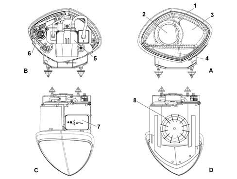
Lamps with exhaust gas dipped/main beam headlamps with dynamic correction
Composition
This type of lamp known as a bi-xenon lamp uses a bulb containing xenon gas for both the dipped and main beam headlamps.The features of this type of lamp are:- increased light efficiency
- greater width and adjustment of the light beam
- less consumption at operating temperature
- longer bulb life
- systematically realigning the direction according to the vehicle load
- dynamically maintaining the alignment to compensate for vehicle pitching
Operation
The light is projected onto the road by means of a large surface, spherical glass lens 70 millimetres in diameter. A partition ensures that the distribution of the light is different for the dipped headlamps and the main beam headlamps. In a raised position it produces the prescribed light - dark limit for the dipped headlamp. Lowered, on the other hand, it gives the main beam headlamp free rein. The partition is activated by a coil which, when supplied, operates a manget that raises or lowers it.The mechanical operation of the lowering or raising movement takes place in real time.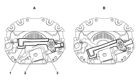
Light cluster
The light cluster has a powerful light beam that, in order to be used to best advantage, requires:- a reflective surface (1) that collects the light beam
- a screen (2) that determines the shape of the light beam
- a spherical lens (3) that determines the depth of the light beam on the road
- controlling the voltage/current value to work at operating temperature
- striking the arc at the electrodes and evaporating the salts when switching on
- switching on, the control unit produces a high voltage (up to 20000V alternating current) capable of producing an arc (electric discharge) between the bulb electrodes.
- arc maintenance, the control unit supplies the bulb, for several seconds, with an excess current that produces the rapid evaporation of the metal halides contained in the bulb.
- Operating temperature, the control unit supplies the bulb with a constant voltage of 80F alternating current.
| during the arc maintenance stage and for less than one second, the intensity of the light beam is greater than compared with normal operation. |
| Make sure that the ignition key is in the OFF position, then disconnect the battery terminal (-) before carrying out any operation on the light clusters. |
Headlamp dynamic automatic correction
On account of their intense brightness, the adoption of xenon bulbs requires an automatic dynamic alignment control system.This system is controlled by an electronic control unit which operates the stepping actuators fitted on each dipped headlamp. The actutaors are controlled by processing the signals coming from the two alignment sensors.The advantages of using an automatic dynamic headlamp alignment control system are:- avoiding dazzling vehicles approaching in the other direction
- stabilizing the area lit to improve active safety
Headlamp alignment correction control unit
It is located under the floor, in the right front section.For further information, (See subassembly ) 5505 INSTRUMENT/GAUGE ELECTRICAL CIRCUITSOperation
The control unit compares the signals coming from the alignment sensors and calculates the vehicle geometry.A "correction" signal is sent to the stepping acutators to adjust the light beam to the vehicle geometry.To prevent oscillations of the dipped headlamp beam in case of:- particular types of roads (cobblestones, unmade roads, etc.)
- sharp movements of the vehicle causes by the driver (clutch release, gear change, etc.)
- Front sensor defective: the calculation of the geometry is made replacing the voltage value read at the sensor with a fixed memorized value.
- Rear sensor defective: the system moves to safety operating mode and keeps the lamps in a pre-set position. This position is the maximum permissible lowered position.
- Failed actuator connection: if there is no control signal, the actuators are placed in the maximum lowered position.
- Control unit faulty: depending on the type of fault, the sytem can remain in the position at the time of the fault or can be placed in the maximum permissible lowered position.
- Decrease in voltage: when the voltage goes below 9 Volts the system remains in the position at the time of the fault.
Direction sensors
They are the resistive type and one is fitted on the front suspension on the right hand side and the other is fitted on the rear suspension on the right hand side.The sensors are supplied by the control unit (5V) and provide a digital signal output (PWM) which supplies the position of the suspension.The connection between the sensor rotation axis and the rear suspension is produced by means of a "connecting rod - crank" system hinged on a self-lubricating ball joint.The crank (1) is an integral part of the actuator and is fixed to the actual rotation axis.The connecting rod (2) is fixed to the lower suspension track control arm (3) by means of a bracket (4).The connection between the sensor rotation axis and the front suspension is the same as for the rear.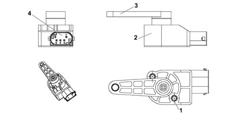
| Pin | Function |
|---|---|
| 1 | earth |
| 2 | not connected |
| 3 | not connected |
| 4 | analogue signal |
| 5 | +5V |
| 6 | PWM signal |
Stepping actuators
They are fitted directly on the headlamps and consist of:- an electric stepping motor
- a screw-female screw reduction unit that transforms the rotary motion of a hinged push rod into linear motion by means of a ball joint.
Headlamp alignment
Each light cluster, according to its function, is distinguished by one of the following markings on the glass:| V - V | vertical, corresponding to the trace of vehicle plane of symmetry; |
| C - C | corresponding to the traces of the vertical planes passing through the reference centres of the light clusters CCR-HC-HCR; (on vehicles with a single light cluster C - C and R - R) |
| R - R | corresponding to the traces of the vertical planes passing through the reference centres of the light clusters R-HR; (on vehicles with a single light cluster C - C and R - R) |
| HC - HC | horizontal corresponding to the height from the ground of the reference centres of the light clusters C-CR-HC-HCR ( on some vehicles HC - HC and H R - H R coincide) |
| H R - HR | horizontal corresponding to the height from the ground of the reference centres of the light clusters ( on some vehicles HC - HC and H R - H R coincide) |
| AC - AC | horizontal below HC - HC and distant from the value shown in the table |
| A R - A R | horizontal below H R - H R and distant from the value shown in the table in appendix 1 (column 4 for the first alignment and column 5 for the alignment with the vehicle bedded in). |
General rules for the alignment of vehicle headlamps in accordane with EEC directive 76/756
Position the vehicle in the "no load" condition with the tyres inflated to the heavy load pressure and with a person in the driver's seat (the mass of the person should be equal to 75 Kg, on a flat, horizontal surface with the reference centre of the headlamps 10 m from the screen). The vehicle should be complete with supplies (fuel, water, oil) and all accessories and tools (that come with the vehicle).Screen
This should consist of an opaque surface on which the following lines have been traced:| V - V | vertical, corresponding to the trace of vehicle plane of symmetry; |
| C - C | corresponding to the traces of the vertical planes passing through the reference centres of the light clusters CCR-HC-HCR; (on vehicles with a single light cluster C - C and R - R) |
| R - R | corresponding to the traces of the vertical planes passing through the reference centres of the light clusters R-HR; (on vehicles with a single light cluster C - C and R - R) |
| HC - HC | horizontal corresponding to the height from the ground of the reference centres of the light clusters C-CR-HC-HCR ( on some vehicles HC - HC and H R - H R coincide) |
| H R - HR | horizontal corresponding to the height from the ground of the reference centres of the light clusters ( on some vehicles HC - HC and H R - H R coincide) |
| AC - AC | horizontal below HC - HC and distant from the value shown in the table |
| A R - A R | horizontal below H R - H R and distant from the value shown in the table in appendix 1 (column 4 for the first alignment and column 5 for the alignment with the vehicle bedded in). |
Light cluster alignment C-CR-HC-HCR
Carry out the alignment of these light clusters on the dipped headlamp light beam, adjusting the height from the ground of the demarcation line between the lit and dark areas and the position of the crossover point between the horizontal section and the inclined section of the demarcation line for both the left and right light clusters.Proceed as follows:- horizontal alignment: act on the alignment device for each light cluster so that the crossover point for the lines C - C and A < SUB > C < /SUB > - A < SUB > C < /SUB > coincides. A maximum movement of 175 mm (1°) on the screen, towards the outside of the vehicle is permissible.
- vertical alignment: act on the alignment device for each light cluster so that the horizontal section of the demarcation line with the line A < SUB > C < /SUB > - A < SUB > C < /SUB > traced on the screen coincides;
Light cluster alignment R - HR
Carry out the alignment for these light clusters for the light beam, adjusting the position of the maximum light brightness zone for both the left and right light clusters.Act on the alignment device for each light cluster so that the centre of the maximum brightness zone coincides with the respective crossovers for the lines R - R and A R - A R. A maximum movements of 175 mm (1°) on the screen towards the outside of the vehicle is permitted.Rapid alignment
To speed up the light cluster alignment operations optical devices that reproduce the characteristics that can be detected on a screen placed 10 m away can be used. The reference lines conforming to the figures for the different vehicles, acccording to the reproduction scales, must be traces on the screens.The use of photometric devices is permitted as long as t| ... DATA ERROR - CROPPED TEXT | Ошибка данных - Текст обрезан ... |
|---|