The Bosch Motronic belongs the category of systems integrated with:
ignition.
phased sequential electronic injection.
The Engine Control Node controls:
air flow at the idling speed set by the electronic throttle;
ignition time, with the benefit of maintaining smooth engine operation even when environmental and applied load parameters change.
The Engine Control Node controls and manages injection so that stoichiometric air/fuel ratio is always within optimum limits.Main system functions are essentially as follows:
self-learning;
system self-adaptation;
self-diagnosis;
Lancia CODE recognition;
cold starting check control;
Combustion - Lambda sensor control;
knock control;
control of enrichment during acceleration;
Fuel cut-off during over-run;
fuel vapour recovery;
control of maximum rpm;
fuel pump control;
Connection with climate control system;
cylinder position recognition;
control of optimum injection time for each cylinder;
Ignition advance adjustment;
idle speed management (also dependent on battery voltage);
throttle opening law management (Sport throttle reponse);
control of engine cooling fan;
control of Cruise control system;
connection to ABS control unit;
connection with automatic transmission control unit;
connection with control panel.
fuel system diagnostics;
catalytic converter diagnostics;
misfire detection;
lambda sensor diagnostics.
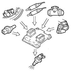
VIEW OF ASSEMBLY
DIAGRAM SHOWING INFORMATION ENTERING/LEAVING ENGINE CONTROL NODE.
OPERATION
Operating strategies
Injection system
The essential conditions to be met by the air-fuel mixture for efficient operation of engines with controlled ignition systems are mainly as follows:
the metering (air/fuel ratio) must be kept as close as possible to stoichiometric levels to assure maximum catalytic converter conversion capacity (max. efficiency).
homogeneity of the mixture, consisting of petrol distributed throughout the air as finely and uniformly as possible.
Information that the Engine Control Node processes to control optimum metering is received by electrical signals emitted by:
air flow meter (debimeter) and air temperature sensor, for the exact quantity of air taken in.
rpm sensor that generates an alternating single-phase signal whose frequency is an indicator of engine rpm. The Engine Control Node uses this signal to detect MISFIRE.
throttle potentiometer, to detect the required acceleration conditions.
coolant temperature sensor on the thermostat.
lambda sensors to measure exhaust gas oxygen content.
Two lambda sensors are located on the exhaust system (one per block) at the preconverter input. Two further lambda sensors are also fitted downstream of the converters to determine converter efficiency and correct injection times for both blocks in time to ensure maximum cat conversion efficiency at all times.
Ignition system
The ignition system is static, inductive discharge type (i.e. without a HT distributor) with power modules located inside the Engine Control Node.The ignition system is arranged so that each coil supplies the spark plugs of the associated cylinder.The advantages of this solution are:
lower electrical overload;
guaranteed constant discharge on each spark plug.
The Engine Control Node contains a memory map with a set of optimum ignition advance values (for the cylinder in combustion phase) that the engine can adopt according to the required speed and engine load.The Engine Control Node corrects the advance value mainly on the basis of:
engine coolant temperature:
intake air temperature.
knock.
Information that the Engine Control Node processes to control the coils is received by electrical signals emitted by:
air flow meter (debimeter) and air temperature sensor, for the exact quantity of air taken in.
rpm sensor that generates an alternating single-phase signal whose frequency is an indicator of engine rpm.
knock sensor (on the upper part of the crankcase between the two heads) to recognise the cylinder with knock and thus correct the ignition advance.
throtle position potentiometer to recognise minimum, partial and full-gas load conditions.
timing sensor.
The Engine Control Node uses the rpm signal to recognise misfiring that could damage the catalytic converters.
Self-learning
The Engine Control Node runs its initialisation program under the following conditions:Engine Control Node removal/refitting or replacement.removal-refitting or replacement of the throttle body built into the DVE.removal-refitting or replacement of the rpm sensor/phonic wheel for detection of misfiring.The values stored by the Engine Control Node are maintained when the battery is disconnected.
System self-adjustment
The Engine Control Node is equipped with a self-adjustment function that is designed to recognize the changes that take place in the engine due to the processes of bedding in and ageing of both the components and the engine itself in time.These changes are memorized in the form of modifications to the basic map and are designed to adapt the operation of the system to the gradual alterations in the engine and the components compared with when they were new.This self-adjustment function also makes it possible to compensate for the inevitable differences in any replacement components (due to production tolerances).The Engine Control Node modifies the basic map in relation to engine specifications when new on the basis of an exhaust gas analysis.The self-adjustment parameters are not deleted if the battery is disconnected.
Self-diagnosis
The control unit self-diagnostic system checks that the system is working properly and indicates any irregularities by means of an MIL warning light in the instrument panel with a standardized ideogram and colour laid down by European regulations. This warning light indicates engine management faults and also faults detected by EOBD diagnostic strategies.The MIL warning light operating (mil) strategy is as follows:
with the ignition on, the warning light comes on and remains on until the engine has been started up. The control unit self-diagnostic system checks the signals coming from the sensors comparing them with the permitted limits.
Fault indication during start up:
failure of the warning light to go out when the engine has been started indicates that there is an error memorized in the control unit.
Fault indication during operation:
the warning light comes on in flashing mode to indicate possible catalytic converter damage due to misfiring.
the warning light comes on in constant mode to indicate the presence of engine management or EOBD diagnostic errors.
RECOVERYFrom time to time the Engine Control Node defines the type of recovery according to the components that are faulty. The recovery parameters are managed by components that are not faulty.
Lancia CODE recognition
When the Body Computer receives an ignition ON signal, it communicates wtih the Engine Control Node to allow start-up. For vehicles with Passive Entry, see [DF55].
Cold starting check
Under cold starting conditions, the mixture naturally becomes leaner and this gives rise to low fuel evaporation at low temperatures:
fuel condensation on inner walls of the intake manifold.
higher lubrication oil viscosity.
The Engine Control Node detects this condition and corrects injection time on the basis of:
coolant temperature.
intake air temperature.
battery voltage.
engine rpm.
The ignition advance is determined solely on the basis of rpm and coolant temperature.During the start-up stage, the Engine Control Node sends an initial simultaneous injection command to all injectors (full-group injection). Once cylinder phase has been detected, normal phased sequential operation can begin.While the engine is warming up, the Engine Control Node controls the throttle body built into the DVL to modulate the amount of air required to ensure engine revs are high enough to keep the engine running.RPM is made to decrease with increasing temperature until the rated level is reached with the engine warm.
Combustion - Lambda sensor check
In EOBD systems, the lambda sensors are all the same type and located upstream of the catalytic conversion system and downstream of the converter. The upstream sensors determine concentration control known as the 1st loop (upstream sensor closed loop). The sensors downstream of the catalytic converter are used to for converter diagnostics and to fine-tune 1st loop control parameters. The second loop is therefore adaptive to make up for production discrepancies and slight drift that upstream sensor responses could experience due to ageing and contamination. This control is known as 2nd loop control (downstream sensor closed loop).
Knock control
The Engine Control Node may delay ignition selectively for a particular cylinder on the basis of a combination of parameters received from knock and timing sensors and:
reduce ignition advance in 3° steps to a maximum of 9°.
update the threshold to take into account underlying noise levels and engine ageing.
During acceleration, the Engine Control Node uses a higher threshold due to the higher engine noise.When the knock disappears, the Engine Control Node increases ignition advance in 0.75° steps until recovery is complete.The Engine Management Node self-adaptive function:
stores advance reductions that are repeated continuously.
adjusts mapping to the various different engine service conditions.
Recovery:
if the timing sensor or knock sensor or Engine Control Node should fail, a variable ignition delay is implemented on the basis of rpm and engine temperature. Maximum ignition delay is always less than 9° engine.
Check on enrichment during acceleration.
In cases of high acceleration demand, the Engine Control Node modifies injection time and throttle position.Recovery:
The Engine Control Node replaces the signal from the faulty air flow meter with a signal from the potentiometer built into the throttle body integral with the DVL.
Fuel cut off during over-run (cut-off)
The Engine Control Node under the following circumstances:
detection of idling status.
rpm above a certain threshold.
deactivates fuel injection on the basis of:
rpm.
engine temperature.
Vehicle speed.
Before reaching idling level, the rpm descent rate is assessed.If this exceeds a certain level, fuel injection is partially re-activated to ensure that engine rpm drops smoothly to idling level.Once idling speed has been achieved, normal functions are resumed.Fuel cut-off is active only 20 seconds after engine start-up.
Fuel vapour recovery.
Fuel vapours (pollutants) collected in the activated carbon filter (canister) are directed to the intake ports to be burnt.This is mediated by a solenoid controlled by the Engine Control Node that holds the solenoid closed for 60 seconds after start-up and then opens it for 90 seconds.During this time period (90 seconds), the la
... DATA ERROR - CROPPED TEXT | Ошибка данных - Текст обрезан ...