74250 - Specifications
F.L.ORE.N.C.E. ELECTRICAL AND ELECTRONIC SYSTEM
In conventional electrical systems, functions are activated with the aid of dedicated point-to-point linesThe increase in the number of electrical/electronic devices on board new cars has given rise to heavier and more complex connections. This is partly due to the complexity of the functions implemented in the burgeoning number of electronic units - which also need to exchange data continually: all this makes new electrical systems more difficult to install and increases the complexity of fault diagnosis.Many problems have been overcome and new electrical systems have been optimised compared to conventional systems by using a network form of connection. This provides a more effective means of managing communication on the board the car and of transferring data between the various subsystems. Information is distributed via serial pathways (buses) that may take the form of: individual wires, twisted wire pairs or even optical fibres.Conventional solution
The three control units (electronic nodes) require a number (N) of wires for each input/output data item in order to perform their function. This multiplied the amount of cable required to the point that systems are made more complex (design and manufacture) and more voluminous (weight, bulk, cost). Some 40 kg of wiring looms are required that stretch for more than 2 km - and this figure could double every 10 years because even now a car could be equipped wiht 20 to 40 electronic control units (ECUs).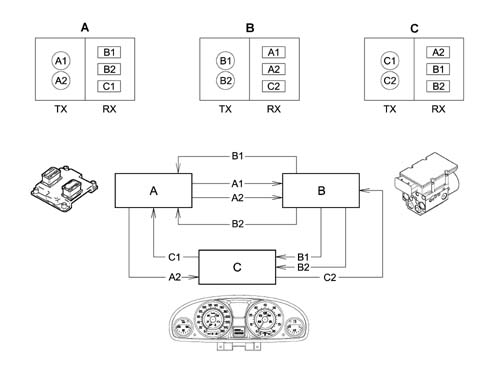
Examples of integation
Engine control unit (NCM) manages: injection, ignition, pollution system, engine cooling control etc.
- current uptake management (lowe battery wear);
- operation of appliances, because they are managed by a single control unit;
- troubleshootng due to self-diagnosti functions in the control units.
Multiplexing solution
This involves exchanging various data signals between various ECUs on a single transmission channel (a principle already used for phone, radio and TV networks): 1 BUS (2 wires) for all data.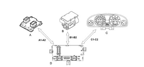
- Reducing and simplifying the wiring
- Reducing the number of sensors (information sharing)
- Allowing ECUs to communicate among themselves.
- transmission channel (wires, optical fibres, radio waves etc.);
- type of signal sent via the channel (voltage, current, light etc.);
- the communication protocol (all the rules that allow management of analogue or digital transmission type, code type, address, transmission order, error detection etc.).
F.L.ORE.N.C.E. ARCHITECTURE
The "F.L.ORE.N.C.E." (Fiat Luxury-car OrientEd Networks and Control Electronics) was designed for optimal management of electrical and electronic functions on top-of-the-range car models.The system interacts with all electrical system functions to directly control body functions (visibility, access, on-board information, comfort, communications etc.) and supports information exchange between traction control systems (engine, braking, gearbox etc.).To optimise the system, each control unit (electronic or electromechanical) is located in a central position in relation to the functions it manages. This allows the power and signal distribution system to be minimised. This is also made possible through extensive use of serial communication networks that allow us to overcome problems of space-saving, reliability, weight and cost.Power is distributed via the junction units and/or fuse boxes. These are connected to control elements (relays and static actuators) to ensure maximum electrical protection and minimum complexity.The wiring architecture is reduced because each system function requires fewer dedicated wires. This is because the wires (ABS, airbag, sidebag) are integral with the front, facia and rear wiring loom to simplify installation operations.Systems of this type offer innumerable benenfits, for example:- sensors included in the various subsystems are available to the network;
- information may be shared;
- sensor duplication is eliminated;
- system flexibility is increased;
- new functions may be added simply by changing the software (developments throughout the car’s lifetime);
- wiring design is simplified and the number of connectors reduced;
- the operational safety of electronic devices is increased to improve the reliability of information transmitted;
- because a diagnostic function is built-in, service operations on electric/electronic components are easier.
- Turn signal/hazard warning flasher (I)
- Headlamp washer timer (I)
- Immobilizer control unit (I)
- IGE control unit (I)
- Infocenter control unit (I)
- Central locking control unit (I)
- Front electric window control unit (I)
- Window control buttons on driver/passenger door (I)
- Rear electric window control unit (I)
- Headlamp alignmnet corrector/fog lamp/rear fog lamp control (I)
- Instrumer light dimmer (I)
- Infocenter control unit (I)
- Remote control receiver (I)
- Volume-sensing sensors for alarm (I)
- Junction node (E)
- Engine bay relay and fuse unit (I)
- Engine compartment junction unit (I)
- Passenger compartment junction unit (I)
- Coolant temperature sensor on engine for instrument functions (E)
- Speedometer generator (E)
- Central front courtesy light (I)
- Courtesy light timer (I)
- Electric rear view mirror control (I)
Network architecture
The structure consists of three CAN communication networks which connect nodes belonging to the three different areas (vehicle dynamic control and bodywork functions) and a certain number of complementary serial lines used for diagnosis and other specific functions:- C-CAN for dynamic vehicle control (high speed)
- B-CAN network for the management of standard body functions (low speed)
- I-CAN network for carrying data and commands relating to on-board information (low speed)
- serial line w for immobiliser recovery
- diagostic line k for Engine Control Node/Automatic Transmission Node
- k diagnostic line for the Air Bag control unit;
- diagnostic line k for NFR
- diagnosic line k for facia area (CSG, CAF)
- diagnostic line k for rear area (NPB, SCS, CPP)
- diagnostic line k for front area (NAC, NBA, CRS)
- A-BUS serial line for managing wipers, safety, exterior lighting. This connects NBC, NIM, CSA, CSP, CTC, CPP, NEC
- NIT/NCL serial line for showing data on display
- NBC/ CFS two-way serial line for testing tail-lights
- CFD/ CFS two-way serial line for testing right tail-light
| Recover line W allows an unlocking code to be sent to the NCM node when the C-CAN network between the Body Computer (NBC) and this node is inefficient |
- audio bus for CD Changer
- audio/video bus for TV tuner
- audio video bus for VHS videocassette player
- aerial leads for: immobilizer, passive entry, parking sensors, radio, GPS, GSM, TV
Wiring
The wiring can be broken down in the following sections:- extension of the ABS wiring to the front wiring
- extension of the airbag wiring to the facia and rear wiring
- extension of the LH and RH front wiring to the front wiring
- extension of the LH and RH rear wiring and courtesy light to the rear wiring
- extension of the engine service wiring to the front and engine wiring
- creation of prewiring on the front driver/passenger side seat and the rear seat
- creation of prewiring on the climate control system unit
- creation of prewiring on the interior rear view mirror
- creation of hi-fi wiring
- connection of all four doors to the rear wiring
CAN structure (CONTROLLER AREA NETWORK)
The electric/electronic systems in the FLORENCE network exchange information by communicating via three physically separate networks known as B-CAN low speed, C-CAN high speed and I-CAN network. The latter is used solely to exchange information between the TV tuner node and CONNECT.The data to be shared by the B-CAN and C-CAN networks are managed by the Body Computer that is equipped with both interfaces and acts as a network gateway.The Body Computer transfers information from the B-CAN category network (low speed) to the C-CAN category network (high speed) and vice versa. Transfer may take place in two ways:- directly: i.e. the entire message is copied to the other network exactly as it is;
- indirectly: with this type of data transfer, the Gateway composes a message for the target network out of the various source messages. One or more messages received from the source network are broken down, the various signals they contain are recomposed in a new message and then sent to the target network.
- H Can for the C-Can network,
- A can for the B-Can network (Can L).
- L Can for the C-Can network,
- B Can for the B-Can network,
- absence of voltage, circuit open or level zero (0)
- presence of voltage; circult closed; or level one (1)
Low speed CAN connection (B-CAN)
Up to 16 nodes may be present on the B-CAN (low speed) network (one for each control unit or electronic unit). All these are connected by means of a pair of wires (BUS CAN) via which a data transmission speed of 50 kbits/sec can be reached.The electronic units shown in the figure are connected to the Body Computer on the B-CAN (low transmission speed) network.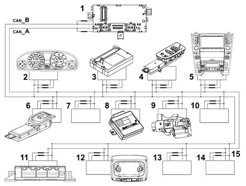
- Wire or CAN line (B) interrupted
- Wire or CAN line (A) interrupted
- Wire or CAN line (
| ... DATA ERROR - CROPPED TEXT | Ошибка данных - Текст обрезан ... |
|---|