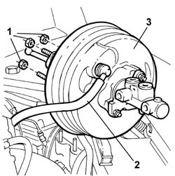
156182 - 3330D04 BRAKE SERVO - R.R. - Includes separation from master cylinder (pump) - for versions with Adaptive Cruise Control (A.C.C.).

Removing ( Refitting ) - Open the boot, remove the cover on the left hand side and disconnect the negative battery lead.     See in Op. 1048A21 AIR INLET HOSE FROM INTAKE TO FILTER - R.R.    See in Op. 1048A28 vacuum air circuit resonator pipe - r+r    See in Op. 1016A42 LEFT CYLINDER HEAD IGNITION COIL COVER - R.R.    See in Op. 1048A11 Air filter assembly - R.R. for versions with automatic transmission 1. Open the band (1a) and release the wiring (1b) on the gearbox bowden cable mounting bracket (1c), then disconnect the electrical connector (1d) for the gearbox input speed sensor.
1. Open the retaining bands and disconnect the three gearbox main wiring connectors.
DescriptionConnector
1 Automatic transmission solenoid valvesL050A
DescriptionConnector
1 Automatic transmission solenoid valvesL050B
DescriptionConnector
1 Automatic transmission solenoid valvesL050C
1. Open the protective flap (1a) and undo the nut (1b) fixing the starter motor supply lead (1c) to the junction node and move the lead between the junction node and the motor aside.
1. Disconnect the connectors (1a) and (1b) for the braking system check control unit (1c) and remove the actual control unit.
DescriptionConnector
1a Braking system check control unit (NBA brake assistance)M052
DescriptionConnector
1b Braking system check control unit (NBA brake assistance)M052
1. Disconnect the connector for the gearbox output speed sensor
1. Undo the two fixing nuts (1a) and remove the mounting bracket (1b) for the gearbox wiring and the starter motor lead.
1. Disconnect the electrical connection for the throttle casing.
DescriptionConnector
.Integrated throttle casing actuatorN075
2. Undo the fixing bolts and remove the throttle casing
    See in Op. 3340A12 A.B.S. hydraulic and electronic CONTROL UNIT - R.R. - Includes bleeding air    See in Op. 3330C30 brake fluid reservoir - r + r and wash inside1. Undo the connectors (1a) for the rigid pipes (1b) between the brake pump (1c) and the ABS control unit and remove them.2. Disconnect the electrical connections at the brake servo (2c) for the brake servo actuator (2b) diaphragm position sensor (2a).
- Proceed as follows, working inside the vehicle:1. Undo the bolts fixing the trim under the dashboard, driver's side.2. Remove the trim under the dashboard, driver's side.
1. Release the steering column universal joint (1a) undoing the bolt (1b) fixing it to the steering box.2. Working on the rear of the brake pedal, release the clips (2a) fastening the brake servo push rod (2b), then release it from the brake pedal.
1. Working inside the vehicle, undo the nuts fixing the brake serov to the bodyshell and to the pedal assembly2. Working in the engine compartment, disconnect the vacuum intake pipe from the brake servo.3. Remove the brake servo/brake pump assembly
- If necessary, separate the master cylinder at the bench. Refitting ( Removing ) - If the master cylinder was removed previously, position it on the brake servo.- Position the brake servo/brake pump assembly in the housing in the engine compartment.- Tighten the nuts fixing the brake servo to the pedal assembly to the recommended torque.
Value - daNmFasteningComponentØ  
.1.4NutBRAKE SERVOM8
- Connect the vacuum intake pipe to the brake servo.- Fit the brake servo push rod in the special housing on the pedal.- Reposition the steering column universal joint securing it by tightening the fixing bolt to the recommended torque.
Value - daNmFasteningComponentØ  
.2BoltSTEERING SHAFT MOUNTINGM8
- Fit the trim under the dashboard, driver's side, in the special housing and secure it using the bolts.- Connect the electrical connections at the brake servo for the brake servo actuator diaphragm position sensor.- Position the rigid pipes between the ABS control unit and the brake pump tightening the connectors to the recommended torque.
Value - daNmFasteningComponentØ  
.1.4ConnectorPIPE FROM PUMP TO HYDRAULIC CONTROL UNITM10
    See in Op. 3330C30 brake fluid reservoir - r + r and wash inside    See in Op. 3340A12 A.B.S. hydraulic and electronic CONTROL UNIT - R.R. - Includes bleeding air- Position the throttle casing and tighten the fixing bolts.
Value - daNmFasteningComponentØ  
.9BoltBUTTERFLY VALVE CASE/S (MPI)M6
- Connect the electrical connection for the throttle casing.
DescriptionConnector
.Integrated throttle casing actuatorN075
- Position the mounting bracket for the gearbox wiring and the starter motor lead and tighten the two fixing nuts.- Connect the connector for the gearbox output speed sensor- Position the braking system check control unit and connect the control unit connectors.
DescriptionConnector
.Braking system check control unit (NBA brake assistance)M052
DescriptionConnector
.Braking system check control unit (NBA brake assistance)M052
- Connect the lead between the junction node and the starter motor and tighten the fixing nut and then close the protective flap.
Value - daNmFasteningComponentØ  
.1.5NutTERMINAL/MOTOR LEADM8
- Connect the three main gearbox wiring connectors, then close the retaining band.
DescriptionConnector
.Automatic transmission solenoid valvesL050A
DescriptionConnector
.Automatic transmission solenoid valvesL050B
DescriptionConnector
.Automatic transmission solenoid valvesL050C
- Connect the electrical connector for the gearbox input speed sensor, then position the wiring on the gearbox bowden mounting bracket and close the band.     See in Op. 1048A11 Air filter assembly - R.R. for versions with automatic transmission    See in Op. 1016A42 LEFT CYLINDER HEAD IGNITION COIL COVER - R.R.    See in Op. 1048A28 vacuum air circuit resonator pipe - r+r    See in Op. 1048A21 AIR INLET HOSE FROM INTAKE TO FILTER - R.R.     See in Op. 0010T64 Brake and/or clutch fluid - Check level and top up, if necessary-- Connect the negative battery terminal and position the cover on the left hand side of the luggage compartment.