74837 - 1032B10 TOOTHED timing BELT - R.R. for timing adjustment or replacement

| Description | Connector | |
|---|---|---|
| 3 | Engine coolant level sensor | K026 |


| Description | Connector | |
|---|---|---|
| 1 | Ignition coil | A030A |
| Description | Connector | |
|---|---|---|
| 1 | Ignition coil | A030B |
| Description | Connector | |
|---|---|---|
| 1 | Ignition coil | A030C |
| Description | Connector | |
|---|---|---|
| 1 | Ignition coil | A030D |
| Description | Connector | |
|---|---|---|
| 1 | Ignition coil | A030E |


| Description | Code | Function | |
|---|---|---|---|
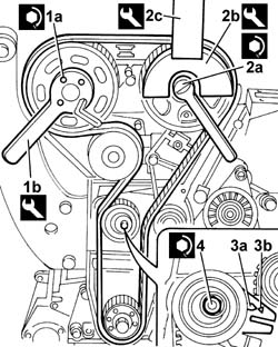
| 1b | Support for counter-torque | 1.860.831.000 | Loosen/tighten exhaust side camshaft drive pulley bolt |
| Description | Code | Function | |
|---|---|---|---|
| 1c | Spanner for rotating timing pullies | 1.860.831.002 | Loosen/tighten camshaft drive pulley bolt |
| Description | Code | Function | |
|---|---|---|---|
| 2b | Counter-torque | 1.860.856.000 | Loosen/tighten inlet side camshaft drive pulley bolts |

| Description | Code | Function | |
|---|---|---|---|
| 1a | Dial gauge support | 1.860.895.000 | T.D.C. check |

| Mark the position of the camshaft caps removed so that they can be correctly positioned when refitting. |
| Check that the camshaft cam profile and the templates are correctly aligned. |
| Description | Code | Function | |
|---|---|---|---|
| 1a | Templates | 1.870.828.000 | Engine tuning |

| The belt is fitted with the arrow facing the direction of rotation of the engine. There are also three references on the belt that should be aligned, during the initial fitting, with the references on the toothed drive pulley and on the inlet and exhaust side toothed driven pullies. |

| Value - daNm | Fastening | Component | Ø | |
|---|---|---|---|---|
| 1b | 2.5 | Nut | MOBILE TIMING TENSIONER | M8 |

| Value - daNm | Fastening | Component | Ø | |
|---|---|---|---|---|
| 1a | (inlet side) 0.9 | Bolt | TIMING DRIVEN PULLIES | M6 |
| Description | Code | Function | |
|---|---|---|---|
| 1b | Counter-torque | 1.860.856.000 | Loosen/tighten inlet side camshaft drive pulley bolts |
| Value - daNm | Fastening | Component | Ø | |
|---|---|---|---|---|
| 2a | (exhaust side) 12 | Bolt | TIMING DRIVEN PULLIES | M12 |
| Description | Code | Function | |
|---|---|---|---|
| 2b | Support for counter-torque | 1.860.831.000 | Loosen/tighten exhaust side camshaft drive pulley bolt |
| Description | Code | Function | |
|---|---|---|---|
| 2c | Spanner for rotating timing pullies | 1.860.831.002 | Loosen/tighten camshaft drive pulley bolt |
| Description | Code | Function | |
|---|---|---|---|
| . | Templates | 1.870.828.000 | Engine tuning |
| Value - daNm | Fastening | Component | Ø | |
|---|---|---|---|---|
| . | 1.5 | Bolt | CAMSHAFT CAPS | M7 |
| Value - daNm | Fastening | Component | Ø | |
|---|---|---|---|---|
| 4 | 2.5 | Nut | MOBILE TIMING TENSIONER | M8 |
| Description | Code | Function | |
|---|---|---|---|
| . | Dial gauge support | 1.860.895.000 | Support |
| Value - daNm | Fastening | Component | Ø | |
|---|---|---|---|---|
| . | 2.7 | - | SPARK PLUGS | M10 X 1.25 |
| Value - daNm | Fastening | Component | Ø | |
|---|---|---|---|---|
| . | 0.9 | Bolt | TIMING BELT PROTECTIVE COVER(S) | M6 |
| Value - daNm | Fastening | Component | Ø | |
|---|---|---|---|---|
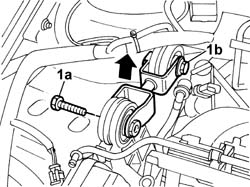
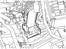
| . | 5 | Bolt | POWER UNIT GEAR BOX END RIGID MOUNT | M10 X 1.25 |
| Value - daNm | Fastening | Component | Ø | |
|---|---|---|---|---|
| . | (to cable centre section) 2.8 | Nut | CATALYTIC CONVERTER (ONE) | M8 |
| Value - daNm | Fastening | Component | Ø | |
|---|---|---|---|---|
| . | (on engine oil sump) 4 | Nut | CATALYTIC CONVERTER MOUNT | M10 X 1.25 |
| Value - daNm | Fastening | Component | Ø | |
|---|---|---|---|---|
| . | (to catalytic converter) 2.8 | Bolt | CATALYTIC CONVERTER MOUNT | M8 |
| Value - daNm | Fastening | Component | Ø | |
|---|---|---|---|---|
| . | (to bracket on bodyshell) 5 | Bolt | POWER UNIT REACTION ROD | M10 X 1.25 |
| Value - daNm | Fastening | Component | Ø | |
|---|---|---|---|---|
| . | (to engine support) 5 | Bolt | POWER UNIT REACTION ROD | M10 X 1.25 |
| Value - daNm | Fastening | Component | Ø | |
|---|---|---|---|---|
| . | 0.9 | Bolt | CAM COVER | M6 |
| Value - daNm | Fastening | Component | Ø | |
|---|---|---|---|---|
| . | 0.9 | Bolt | IGNITION COIL/REEL | M6 |
| Description | Connector | |
|---|---|---|
| . | Ignition coil | A030A |
| Description | Connector | |
|---|---|---|
| . | Ignition coil | A030B |
| Description | Connector | |
|---|---|---|
| . | Ignition coil | A030C |
| Description | Connector | |
|---|---|---|
| . | Ignition coil | A030D |
| Description | Connector | |
|---|---|---|
| . | Ignition coil | A030E |
| Description | Connector | |
|---|---|---|
| . | Engine coolant level sensor | K026 |