939003529 - 5505 INSTRUMENT/GAUGE ELECTRICAL CIRCUITS
Structure of electrical/electronic system
The eletrical equipment on this vehicle uses the F.L.Ore.N.C.E. structure developed specifically to incorporate the most up to date electronic functions in the optimum way.This structure makes up the car''s "nervous system", directly controlling all the bodywork functions (access control, visibility, on board information, comfort, etc.) and converses with the different chassis and power unit subsystems improving system fault diagnosis, reliability, weight and cost.A further advantage compared with traditional systems is the simplified installation through the reduction in the number of control units (for the number of functions offered to customers) and the number of power and signal connections through the extensive use of serial communication networks (3 CAN twin wire communication networks, 1 single wire LIN subnetwork, 1 A-BUS single wire subnetwork).The distribution of the power takes place by means of four junction units and relay/fuse boxes, connected to the control elements (static actuators and relays). These control units also act as an interconnection for the various wiring and electrical distribution to ensure the maximum level of electrical protection and the minimum degree of wiring complexity.Electronic components
The main electronic components managed by the "F.L.Ore.N.C.E." structure are listed below:| Electronic components | Wiring diagram code |
|---|---|
| Body Computer Node | M001 |
| Engine Management Node | M010 |
| Automatic Transmission Node | M055 |
| Robotized Gearbox Node | M054 |
| Gearbox Selector Node | M053 |
| Electric Steering Lock Node | M089 |
| Volumetric Sensors Control Unit | G010 |
| Anti-theft Alarm Control Unit | P090 |
| Instrument Panel Node | E050 |
| Auxiliary Instruments | E020 |
| Info Telematic Node | P020 |
| CD-Changer Node | P075 |
| Bluetooth Control Unit Node | M162 |
| Hi-fi Bose audio amplifier | P070 |
| Radio Receiver Node | P020 |
| Steering Wheel with radio controls Node | D047 |
| Luggage Compartment Node | M063 |
| Driver''s Door Node | M066 |
| Passenger Door Node | M067 |
| Wiper Electronic Control Unit | N015 |
| Dusk and rain sensor | P065 |
| Braking Node | M050 |
| Steering Angle Node | K058 |
| Slewing Node | K074 |
| Air Bag Node | M060 |
| Climate Control Node | M070 |
| Tyre Pressure Control Unit | M047 |
| Parking Sensor Node | M084 |
| TEG Reader Node | H003 |
Control modules
The F.L.Ore.N.C.E. structure provides for the inclusion of the user controls inside the switch holder modules, following the functional grouping logic and the proximity of the most frequently used controls.| Control modules | Wiring diagram code |
|---|---|
| Driver''s door control module (front and rear electric windows, driver''s door folding mirrors) | H044 |
| Passenger electric windows control | H050 |
| Lights Control in dashboard (fog lights, rear fog lamps, parking lights, km zeroing, headlamp alignment) | H090 |
| Starting control in dashboard | H002 |
| Steering column switch unit module (controls for lights, screen washing and wiping, cruise control, trip meter, lighting adjustment, vehicle set up) | H005 |
| Controls on tunnel (central locking, hazard warning lights, ASR and VDC exclusion) | H035 |
| Controls in courtesy light (controls for courtesy lights, boot opening, volumetric and parking sensor exclusion, telematic and emergency controls) | G010 |
| Electric seat controls | H066, H067 |
Electric power control unit (fuse boxes)
There is a wired type control unit in the luggage compartment (CVB) and three fuse/relay boxes constructed using "sheared circuit" technology:- Dashboard Control Unit (CPL) in dashboard- Engine Compartment Control Unit (CVM) in engine compartment- Battery and Optional Fuses Control Unit (CBA, CFO) above the battery| Fuse boxes | Wiring diagram code |
|---|---|
| Battery Control Unit CBA | B099 |
| Optional Fuses Control Unit CFO | B098 |
| Engine Compartment Control Unit CVM | B001 |
| Dashboard Control Unit CPL | B002 |
| Luggage Compartment Control Unit CVB | B045 |
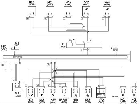
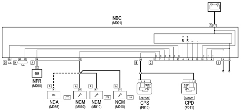
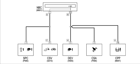
Network architecture
The structure comprises three CAN communication networks connected by a gateway for transferring shared information:- C-CAN (low speed: 500 kbit) for the dynamic control of the vehicle- B-CAN (high speed: 50 kbit) for managing bodywork functions- CAN for multimedia functions.The gateway for communication between the C-CAN and B-CAN is located in the Body Computer.The fault diagnosis of the nodes connected to the B-CAN is carried out via the CAN, whilst for those connected to the C-CAN this is carried out by means of the specific K lines (5 ISO serial lines for fault diagnosis).The K lines and the B-CAN flow into the EOBD diagnostic connector located on the Body Computer.There are also the W line, ISO 5 serial for immobilizer recovery and the A-BUS line, the ISO 5 serial for the alarm, wiping, lighting, tyre pressure monitoring functions.C-CAN.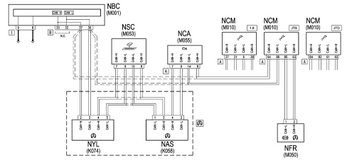
Replacing and initializing network nodes
Some of the CAN nodes are programmed with default settings which the customer will discover on acquiring the vehicle.The nodes storing this information are the:- Body Computer;- Instrument Panel Node;- Bluetooth Control Unit Node- Climate Control System Control Unit;- Driver''s and Passenger Door Nodes ( HIGH version) or Front Door Node ( LOW version);- Steering Lock Node.| If the Body Computer is being replaced, an "identical copy" of the Body Computer must be obtained from the Parts Dept as a V.O.R. order supplying the vehicle chassis number: this copy will contain all the default settings entered when the vehicle was new which are stored in the Parts Dept. database for the vehicle chassis number. |
| If the Instrument Panel or the Climate Control System control unit is being replaced, the Parts Dept. will send a "virgin" component: once fitted; the initial default data must be transferred to it by carrying out the "PROXI ALIGNMENT" procedure using the Examiner. |
| If one of the other nodes described above is being replaced, no initialization operation is required. However, always check that the system has not picked up errors during the removing-refitting operations, etc. using the Examiner. |
CONTROL UNIT ON BATTERY (CBA)
This connects the battery terminal to the starter motor lead and to the first level power fuses that rotect the supply for the engine compartment junction unit (CVM), the dashboard junction unit (CPL), the luggage compartment junction unit (CVB), where the second level protective fuses are located.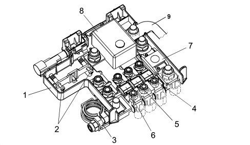
| No. | CODE | Fuses in junction unit (CBA) | Amperage | Connector |
|---|---|---|---|---|
| 4 | F71 | for dashboard control unit (CPL) | 70A | C |
| 5 | F72 | for robotized gearbox control unit | 60A | D |
| 6 | F73 | for pre-heating control unit (JTD only) | 60A | E |
| 7 | F70 | for engine compartment control unit (CVM) | 150A | B |
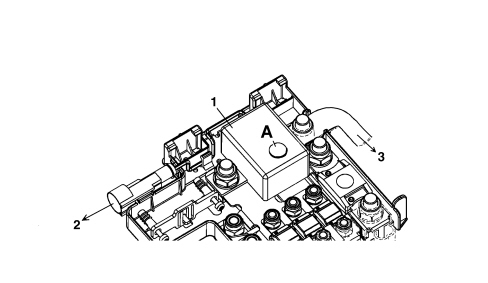
Automatic battery disconnection device
The CBA incorporates an automatic battery disconnection device in series to the battery terminal capable of interrupting the power supply to the starter/recharging motor lead in emergencies.This interruption is controlled by the inertia switch in the same way as for the fuel pump.| If the inertia switch is operated with a consequent interruption in the power supply, the device must be "re-armed" by pressing the yellow button A. |
OPTIONAL FUSES JUNCTION UNIT
Next to the CBA there are two additional fuses for versions which have an additional heater (JTD only): F74 (30A) and F76 (50A).ENGINE COMPARTMENT JUNCTION UNIT (CVM)
Electro-mechanical control unit including fuses (Maxi and Mini), relays and circuits for connecting the front wiring and radiator pre-wiring.This wiring is connected to the control unit through fixed couplings. There is a chamber under the protective cover for housing any further connectors/relays/fuses.There is a fastening on the lower cover for sealed fuse holder connectors (maxi and auto type).
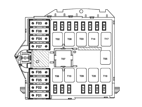
| CODE | COMPONENT | amp. | TYPE |
|---|---|---|---|
| F-1 | FUSE CPL and CVB | 70 | MAXI |
| F-2 | CLIMATE CONTROL FAN FUSE | 40 | MAXI |
| F-3 | FUSE STEERING LOCK (NBS) | 20 | MAXI |
| F-4 | FUSE BRAKING NODE (NFR) | 40 | MAXI |
| F-5 | FUSE BRAKING NODE (NFR) | 40 | MAXI |
| F-6 | FUSE RADIATOR FAN 1 | 40 | MAXI |
| F-7 | FUSE RADIATOR FAN 2 | 50 | MAXI |
| F-8 | FUSE ROBOTIZED GEARBOX PUMP | 30 | MAXI |
| F-9 | FUSE HEADLAMP WASHER | 20 | mini |
| F-10 | FUSE HORNS | 15 | mini |
| F-11 | FUSE I.E. SECONDARY SERVICES |
| ... DATA ERROR - CROPPED TEXT | Ошибка данных - Текст обрезан ... |
|---|