939003527 - 5040 AIR CONDITIONING CASING AND COMPONENTS
INTRODUCTION
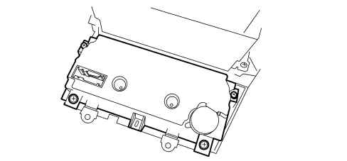
The climate control system makes it possible to alter the features of the air introduced into the passenger compartment (temperature, humidity) designed to create and maintain a high level of comfort whilst driving.Climate control system components
The climate control system components are illustrated in the diagram.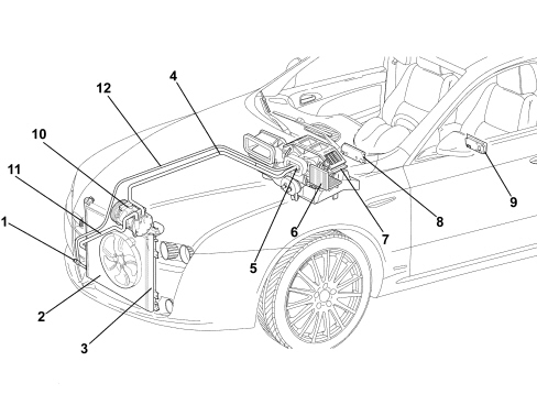
Operating principle
The aim of refrigeration equipment is to absorb heat from an environment. In order to do this an air conditioner has recourse to certain fluids (known as refrigerants) capable of cooling down (lowering their temperature) and changing state (from liquid to gas) when they are subject to a large drop in pressure, expanding. They are therefore capable of absorbing heat from the environment. When the temperature increases thereby also increasing the pressure, they change state, another time, from gas to liquid, and condense.The first problem is therefore to liquefy this gas which can be achieved simply by bringing it to a temperature below that of evaporation (or boiling) which, as has already been stated, is -26°C at atmospheric pressure for R134a.In order for this to be achieved at ambient temperature which, in our case, may be rather high (in the engine compartment), it is necessary to increase the evaporation point of the gas so that it remains liquid until the moment it is made to expand to produce the desired refrigerant effect.To raise the boiling point of the gas its pressure must be increased, at the same time, decreasing the temperature.In order for this to take place the system requires a certain amount of power. This power, supplied by the compressor, is subtracted from the power produced by the engine.The operating principle of the refrigerant cycle phases in the air conditioning system for a motor vehicle can be summed up as follows.The gaseous R134a refrigerant is drawn in by the compressor at a pressure of between 0.5 and 2 bar and is compressed at a value of between 10 and 17 bar. The boiling point at these pressures is around 60 °C.This fluid, heated by the compression stage at 80 - 100 °C, always in a gaseous state, in the compressor where, through the effect of the cooling air flow (produced by the vehicle moving forward or through the action of the fan) that passes through, reaches condensation point, changing at high pressure to a liquid state.Later on the refrigerant passes through a filter which has three functions: to trap the impurities, absorb the dampness contained in the circuit and work as a reserve reservoir for the actual refrigerant.The refrigerant reaches the expansion valve, where it is introduced into the evaporator where the pressure is around 1.5 atm. (1.52 bar). At this pressure the liquid/vapour system saturated with the refrigerant fluid is in equilibrium at a temperature of about -7 °C. At the same time, the air that passes through the evaporator (through the action of a fan), being at a considerably higher temperature than the refrigerant fluid it contains, causes it to boil and evaporate completely by imparting heat. On cooling, the air deposits some of the dampness it contains on the evaporator fins in the form of droplets which are collected in a chamber and drained off from the vehicle.The cooled and dehumidified air is sent inside the vehicle. The refrigerant is drawn in by the compressor again at the evaporator outlet, thereby giving rise to a new cycle once again.The route of the refrigerant fluid can be summarized as follows:- In the compressor - the fluid coming from the evaporator is gaseous (temp. -5, -7°C, pressure 0.5 - 2 bar). Compression phase - the gaseous fluid is overheated (temp. 80 -100 °C, pressure 10 -17 bar).- Condensator - Compression phase: the fluid gives off heat to the outside, cools down and returns to a liquid state (temp. 40 -60°C, pressure 10 -17 bar).- Thermostatic expansion valve - Expansion phse - the fluid loses pressure (0.5 - 2 bar, possibly even 3 bar) becomes a gas + liquid mixture; the temperature is low, typical of air conditioning.- Evaporator - Evaporation phase - the fluid becomes completely gaseous because the hot air driven by the fan finds itself at a higher temperature than the refrigerant fluid and causes it to boil and evaporate completely giving off heat. The temperature is low, typical of air conditioning (pressure 0.5 - 2 bar).Types of system
This vehicle can be equipped with different climate control systems for the passenger compartment:- manual climate control- dual zone automatic climate control- triple zone automatic climate controlManual climate control: the user sets the air temperature, distribution and flow rate and they remain like that until they are altered by the user later on.Automatic climate control (dual/triple zone): the user can set the parameters and select automatic system management. If they so wish, the user can preseve the facility to manage the system manually.In addition, the automatic climate control system on this vehicle is the dual zone type (driver''s zone and front passenger zone) or triple zone (driver''s zone, front passenger zone and rear seat zone), in other words the system has dual controls for the driver and the passenger and is capable of managing the settings for the two users separately, varying the air temperature and distribution parameters (the flow rate cannot be different in the zones) with a certain degree of independence.MANUAL CLIMATE CONTROL
The manual climate control system control panel is illustrated in the diagram below.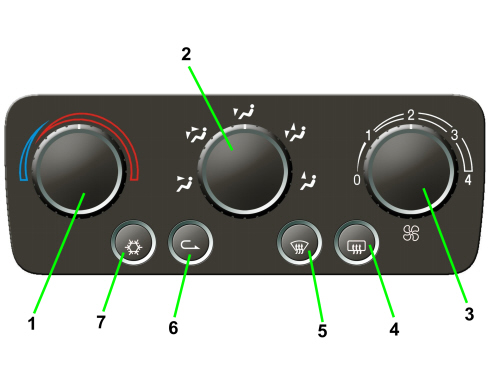
| Pin | Signal |
|---|---|
| 1 | earth |
| 2 | direct power supply (from F39) |
| 3 | n.c. |
| 4 | n.c. |
| 5 | n.c. |
| 6 | n.c. |
| 7 | n.c. |
| 8 | additional heater control signal PTC1 |
| 9 | additional heater control signal PTC2 |
| 10 | fan relay feed |
| 11 | compressor engagement positive (output) signal |
| 12 | B-Can A line |
| 13 | B-Can B line |
| 14 | recirculation actuator control |
| 15 | recirculation actuator control |
| 16 | recirculation actuator control |
| 17 | recirculation actuator control |
| 18 | n.c. |
| 19 | distribution actuator control |
| 20 | distribution actuator control |
| 21 | distribution actuator control |
| 22 | distribution actuator control |
| 23 | mixture actuator control |
| 24 | mixture actuator control |
| 25 | mixture actuator control |
| 26 | mixture actuator control |
Operating strategy
The manual air conditioning also allows the user to manage the temperature and the intake of air into the passenger compartment using the control knobs and buttons.The following parameters/functions can be altered manually:- Temperature- Distribution in 5 positions- Fan speed.- Compressor enablement- Defrosting/demisting function- RecirculationThe transmission of the air mixing, air distribution and recirculation commands from the knobs to the climate control casing takes place by means of electric motors.The compressor can only be activated if one of the fan speeds is switched on.AUTOMATIC CLIMATE CONTROL
The automatic climate control system is managed by a control unit which is capable, thanks to an extremely sophisticated operating logic, of controlling the temperature in two zones of the passenger compartment heating or cooling the air to produce the desired comfort level.The climate control system automatically adjusts the following parameters/functions:- Air temperature at the driver''s/passenger side vents- Fan speed (continuous variation)- Driver/passenger side air distribution- Engagement of compressor- RecirculationControls
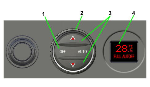
The user interface for this control unit has the following layout.Dual/triple zone front controls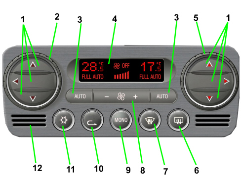
| Pin | Signal |
|---|---|
| 1 | earth |
| 2 | direct power supply (from F39) |
| 3 | actuator positive power supply |
| 4 | fan adjuster positive power supply |
| 5 | earth for evaporation sensor |
| 6 | solar sensor power supply |
| 7 | additional heater control signal PTC1 |
| 8 | actuator BUS communication line |
| 9 | additional heater control signal PTC2 |
| 10 | B-Can A line |
| 11 | B-Can B line |
| 12 | n.c. |
| 13 | signal from evaporator sensor |
| 14 | n.c. |
| 15 | compressor engagement positive (output) signal |
| ... DATA ERROR - CROPPED TEXT | Ошибка данных - Текст обрезан ... |
|---|