939003534 - 5560 INSTRUMENTS
INTRODUCTION
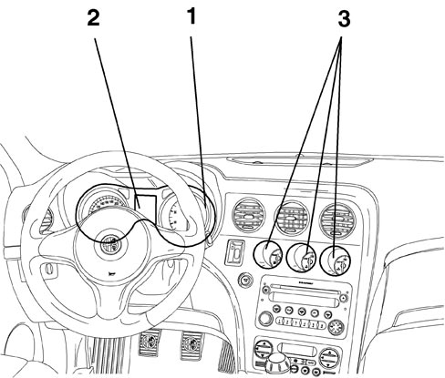
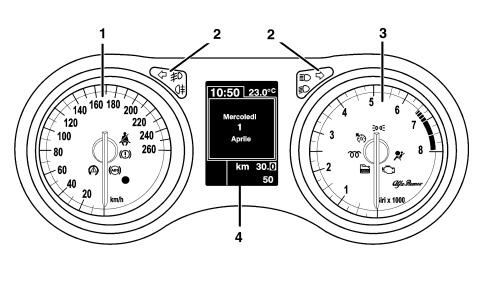
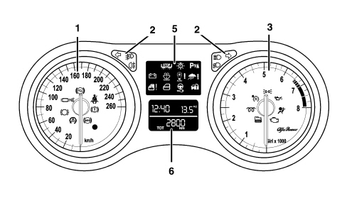
The instruments on board the vehicle in question are positioned ergonomically within the arc of the steering wheel with the auxiliary instruments in the centre of the dashboard and a large high resolution display that is very bright.The lighting can be adjusted and there is a dusk sensor to differentiate between daytime and nightime conditions.The following innovative features have been introduced on this vehicle: instruments aimed at the driver with three dimensional graphics, lit indexes, white graphics, reconfigurable auxiliary instruments.1. main instrument panel2. display3. centre instrument clusterThe panel comes in two versions: HIGH panel and LOW panel.HIGH panelLOW panel1. Speedometer2. Warning lights3. Rev counter4. Reconfigurable matrix LCD (HIGH only)5. Warning lights (LOW only)6. Negative contrast alphanumerical LCD (LOW only)The instruments also contain:- buzzer;- light sensor for automatic adjustment (day/night) of the instrument brightness.Warning and fault warning lights
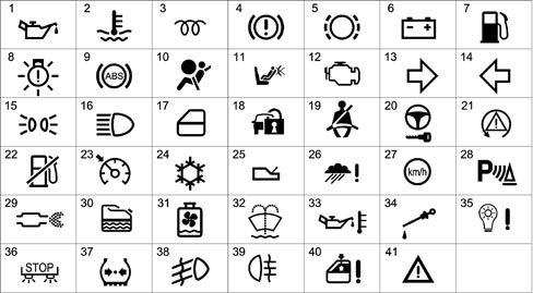
The warning lights are shown by means of the special LED or in the centre display. The diagram summarizes the symbols used:1 Insufficient oil pressure2 Engine coolant overheating3 Heater plugs4 Handbrake applied - insufficient brake fluid - EBD failure (with ABS warning light activated)5 Brake pad wear6 Alternator failure7 Fuel reserve8 Exterior lighting failure9 ABS failure10 Air Bag failure11 Passenger Air Bag deactivated12 EOBD (engine management system failure)13 Right direction indicator14 Left direction indicator15 Side lights16 Main beam headlamp17 Door/s open18 Immobilizer failure (CODE)19 Seat belts not fastened20 TEG Reader failure21 VDC22 Inertia switch operation23 Cruise Control24 Danger - Ice signal25 Automatic/robotized transmission failure26 Rain sensor failure27 Speed limit warning28 Parking sensor failure29 DPF filter blocked30 Water in diesel filter sensor31 Radiator coolant level32 Windscreen washer fluid level33 Engine oil overheating34 Engine oil level35 Dusk sensor failure36 Brake lights failure37 Insufficient tyre inflation pressure38 Fog lights39 Rear fog lamps40 Windows anti-crush safety device failure41 General failureHIGH INSTRUMENT PANEL
Speedometer
The system calculates the value of the actual vehicle speed starting with the values supplied by the sensors on the two drive wheels and the value of the actual circumference of the wheels, supplied by the on board computer. The electronic control and operating structure is achieved by means of a microprocessor.The speedometer reading is produced by means of a stepping motor. | The instrument panel increases the value of the effective speed slightly, for safety reasons, but never exceeds the maximum tolerance laid down by the directives for the countries where the vehicle is sold. |
The actual speed of the vehicle is provided even if one or two of the drive wheel sensors is broken.If there is a fault in the vehicle speed sensor the instrument panel returns the indicator to the rest position.Rev counter
The control and operating electronics use a microprocessor with the reading produced using a stepping motor guaranteeing precision and continuity throughout the entire scale and a reading in extreme operating conditions.The rev counter on diesel and petrol versions differs through the maximum end of scale value (6000 rpm for diesel versions and 8000 rpm for petrol versions) and through the start of the red danger zone (4500 rpm for diesel versions and 6800 rpm for petrol versions).Buzzer
A buzzer offers the possibility of managing signals of different intensity for the following functions:- Signalling doors open with the vehicle moving- Signalling handbrake applied with the vehicle moving- Signalling parking sensors- Warning speed limit exceeded- Acoustic feedback on activation of functions using buttons- Acoustic feedback on memorizing of seat and exterior mirrors position- Signalling of reverse gear and automatic/robotized transmission safety position- Signalling of driver''s door open with TEG inserted- Feeback on warnings/alarms shown in the displayBrightness sensor
This sensor, located in the speedometer panel, has the task of measuring the environmental light conditions and of sending this information (day or night) to the Body Computer which, on comparing this information with the status of the side lights, will select the suitable configuration for the vehicle interior lighting (daytime or nightime mode).With this information available, the behaviour of the instrument is as follows:- In "daytime" mode the display can be adjusted to 8 settings, the graphics are switched off, the index lighting is 100% and cannot be adjusted.- In "nightime" mode the display, the graphics and the indexes can be adjusted to 8 settings and the level set will be transmitted to the components that regulate the brightness (climate control display, radio display).Keys
The following buttons are fitted on the left steering column switch unit lever:- “MENU”- “MENU +”- “MENU -“and carry out the following functions: Management of the setup menu; dimming and activation/deactivation of the night panel.The following buttons are fitted on the right steering column switch unit lever:- “TRIP”- “TRIP UP”- “TRIP DOWN”and are used for the management of the Trip Computer and the TPMS wheel check screen.The button dedicated to the operation of the "km" trip meter is located in the left panel and has the function of zeroing it through a long press.Reconfigurable matrix display
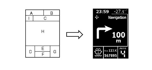
The visible area of the display is 50 mm wide and 70 mm high with a resolution of 124x174 pixel and is divided into zones as illustrated in the diagram below:A - TimeB - Outside temperatureC - Function displayedD - Failure symbols/ideograms (two tone red/amber area)E - Trip meterF - Total milometerG - Automatic/Selespeed transmission information (if present)H - Messages, Trip Computer, bar graph, Set-up menu, Service, Date, vehicle image in 3D, Radio info, Navigation info, etc.I - Function displayed identification symbolMain functions (high)
Trip computer and tpms check
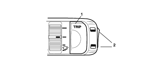
There are two TRIP modes:- TRIP A (with manual reset only);- TRIP B (with manual or automatic reset from key-on that can be set using the setup menu) divided and with the sequence described below, activated using the special button.TRIP A:- Range- Distance travelled - A- Average consumption - A- Instant fuel consumption- Average speed - A- Journey time - ATRIP B- Range- Distance travelled - B- Average consumption - B- Instant fuel consumption- Average speed - B- Journey time - BEvery TRIP screen simultaneously displays two TRIP items activated at that time (TRIP A or B); these items are displayed one in the top part of the screen and the other in the bottom part.Entry into the Trip Computer ambient takes place by pressing the TRIP button on the steering column switch unit windscreen wiper lever.The first time the TRIP is pressed the figures for Trip A are displayed and the second time it is pressed those for Trip B are shown.If the TPMS option is present, the third time it is pressed the tyre inflation pressure check screen is displayed, otherwise the Trip ambient is exited.To move from one Trip Computer figure to the next, the rocker switch on the windscreen wiper lever must be operated.1. TRIP button activation2. TRIP function buttonsThe Trip is reset by pressing the TRIP button for a while whilst Trip A or Trip B is displayed.Setup menu
For safety reasons, the complete menu cannot be accessed when the vehicle is moving.When the NIT is present on the version, the menu will be shown on the NIT display.All the possible setup menu options, the choices available and the factory (default) setting for each selection are listed below (some options may or may not be present depending on the vehicle trim level).Speed limit:XXX: numerical value of the speed set.YYY: Unit of measurement set.Default: OFFDefault ON: 130 km/h or equivalent in mphDusk sensor setting adjustmentBargraph in display - adjustment to 3 levelsTRIP B reset modeDefault: ManualClock adjustmentDefault: 00:00The hour flashes.When the time is <10 the "0" at the front should not be displayedDefault: 00:00The minutes flashTime mode“24h” or “12h”Default: 24hDate adjustmentThe year flashesThe default is the year when the instrument panel software was released, e.g.: 2005The months flashDefault: 01The days flashDefault: 01Audio repetitionDefault: OFFBoot unlocking together with unlocking of all the doorsDefault: OFFUnlocking of the driver''s front door onlyDefault: OFFAutomatic locking of doors and boot above 20 km/hDefault: OFFUnit of measurement settingUnit of measurement for distances: default: kmUnit of measurement for consumption: default: l/100kmUnit of measurement for temperatures: default: °CLanguage settingThree items are displayed at a timeVolume of buzzer for alarms/failures/warningsDisplay with bar graph - 8 setting adjustmentButton pressing buzzer volume (roger beep)Display with bar graph - 8 setting adjustmentService interval (km/miles/days)XXX: ValueYY: Unit of measurement set for distances, ("km" or "mi")Sealt Belt ReminderDefault: OFFLighting that can be dimmed with brightness sensor and night panel
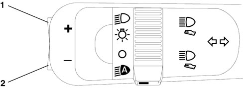
The HIGH version allows the user to adjustment the brightness of the graphics, indexes, instrument panel display, instruments, radio and climate control by pressing the "Menu +" and "Menu -" buttons located at the side on the lights lever.1 Menu +2 Menu –The indexes are always lit up at the key-on.Two different brightness settings can be adjusted by the user and memorized by the instrument, one for the daytime mode and one for the nightime mode.The Night Panel function can be activated in the "Nightime Mode " status by pressing the "Menu -" button for about 2 seconds.The activation of the Night Panel switches off the backlighting of the rev counter panel and the instrument panel graphics, whilst the backlighting of the speedometer panel and the display remains activated and can be dimmed.Once activated, the Night Panel function can be deactivated in the following ways:- By pressing the "Menu + " button for about 2 seconds- automatically at each key-OFFDisplay of information relating to planned maintenance
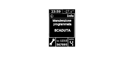
When the programmed maintenance (service) is close, the message is automatically displayed at the key on (after the initial check procedure) followed by the number of kilometres, miles or the days until the next service is due.The display of the programmed maintenance information can also be shown if the user requests by selecting a special item in the setup menu. In this case the display is possible, irrespective of the intervals.The starting date for the mileage is 20,000 km (or 12,000 miles).Display logic for instrument panel in automatic service conditions:The first message is displayed once at the key on, if one of the following conditions occurs:- the kilometres or miles (depending on the unit of measurement set) until the next service are equal to or less than the limit- there are 30 or less days until the next serviceLater on the message is displayed only once at the key-on, each time the value is equal to or less than the following partial level values:1800, 1600, 1400, 1200, 1000, 800, 600, 400, 200, 100, 50 km (or partial corresponding levels in miles) and 27, 24, 21, 18, 15, 12, 9, 6, 3 days; no longer displayed at subsequent keys-onThe moment the service interval is reached the service message is displayed at each key-on: example:Display logic as requested by the driver:The information relating to the programmed maintenance can be displayed at any time by selecting the relevant item using the SET-UP MENU. | Once all 9 services have been exhausted, no message is displayed automatically and it is no longer possible to select the item from the set-up menu. |
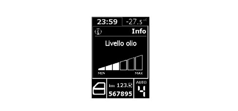
Display of engine oil level
Two seconds after the key-ON the display shows information concerning the engine oil level, for about 3 seconds, by switching the six "bars" on/off (bargraph). The maximum oil level is represented by all the bars lit.The MIN and MAX values shown on the display correspond to the MIN and MAX levels on the oil dipstick, e.g.:The gradual switching off of the "bars" indicates a decreasing oil level.If the oil level is below the minimum recommended level, the screen described above is not displayed and a "minimum oil level" message appears in its place.If the oil level is beyond the maximum level, then an "oil level too high" message will appear.At the first key-on after the bat| ... DATA ERROR - CROPPED TEXT | Ошибка данных - Текст обрезан ... |
|---|