939003507 - GENERAL REMARKS - CLUTCH
CLUTCH - FLYWHEEL ASSEMBLY
1. Clutch2. FlywheelThe clutch-flywheel system on the 1.9 JTS/2.2 JTS engines is supplied by SACHS and has the following specifications:- dry, single plate clutch with thrust operation- dual mass type shock absorbing flywheel.Clutch assembly
Dry, single plate type clutch with hydraulically operated thrust release, coaxial internal actuator and XTend plate wear recovery device.Xtend plate wear recovery device
The automatic recovery of the clutch plate wear clearance makes it possible to keep the clutch pedal free play constant.The automatic wear recovery mechanical device known as XTend has the following specifications:- independent of tolerances and does not require adjustment;- exact recovery of plate wear;- robust system with simple mechanical parts.The device consists of:- compression spring;- clip;- positioning rings;- adjuster;- adjuster traction spring;- traction spring for positioning rings;Operating principle
During usage the thrust plate and the recovery mechanism move towards the flywheel (A).The slit corresponding exactly to the wear of the seal (B) forms under the compression spring.The adjuster slides and detects this wear (C).With the clutch released (D), the lower positioning ring slides and closes the slit under the compression spring detected by the adjuster (E).On the new engagement, the wear is recovered and the diaphragm spring returns to its original position.Driven friction plate
The driven disc fitted on the Sachs flywheel/clutch assembly is the pre-damping flexible type which contains springs with a flexible coupling function.The benefits of adopting this component are:- reduction in hub wear;- decrease in angular and radial lack of balance between the engine and gearbox;- improved uncoupling in neutral with the use of a reduced travel pre-shock absorber;- reduction in radial forces caused by offset between crankshaft and gearbox.Twin mass damping flywheel
This flywheel is the twin mass damping type consisting of two masses, one forming one piece with the crankshaft and the other with the gearbox main shaft, via the clutch plate. There is a double rigidity flexible torsional damping system between the two masses made up of two systems with differing flexible rigidity springs and an epicyclic gear immersed in grease. The feature of this flywheel is the variation in the torsional resonance which, compared with a normal flywheel, is below the engine operating speed and improves driving comfort and reduces the transmission of irregular loads to the gearbox.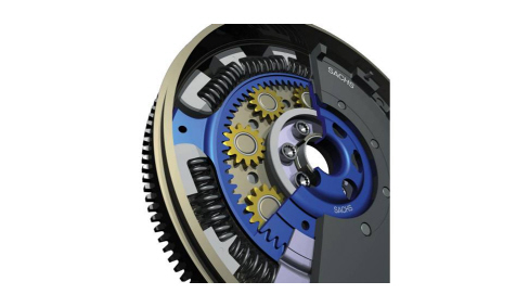
Operation
The kinematic route of the power transmission is illustrated in the diagram.1. Main flywheel2. Secondary flywheel3. Wheel4. Planet wheel5. Axial bearing6. Radial bearingThe crankshaft transmits the power to the main flywheel.The pads receive the power from the main flywheel and transfer it to the springs;The spring system acts as a damper for the torque variations.The pads-springs system transmits the power to the wheel which, in turn, transmits it to the secondary flywheel.The epicyclic system consists of the gear train carrier (main flywheel), the ring gear with internal teeth (wheel) and eight satellite gears.This gearing behaves like a second damping element as the system is immersed in grease and the satellite wheels have a rotation inertia.With this type of flywheel the damping of the torque fluctuations are in two stages, capable of reducing the vibrations and roughness of the transmission of power more effectively and with better direction.


