939003520 - GENERAL REMARKS - BRAKES
SPECIFICATIONS
The braking system is the power assisted hydraulic type, comprising two crossover, independent ciruits (each circuit acting on one front wheel and the diagonally opposite rear wheel) to ensure braking and stability even if one of the circuits fails.The system is also equipped with the following assisted braking and steering systems:- ABS: anti-lock brakes;- EBD: electronic brakeforce distribution between the front and rear wheels;- ASR: traction control via management of the brakes and engine control unit;- MSR: engine brake control by means of engine control unit management;- VDC: vehicle electronic stability control;- HBA: automatic increase in braking pressure during emergency braking;- Hill Holder: assisted hill start system that keeps the vehicle braked while parked on slopes and automatically releases the brakes when the driver wishes to set off.The vehicle is equipped with an ABS/EBD brake control system.The ABS is fitted parallel to the hydraulic braking system so that should it not work braking would still be guaranteed.The ABS incorporates the EBD function (Electronic Brake force Distribution) therefore the hydraulic system does not have a rear load proportioning valve.ABS/EBD SYSTEM
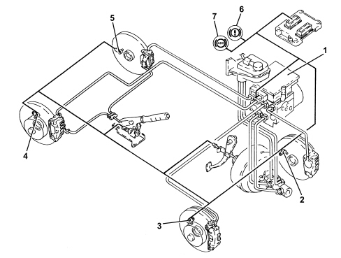
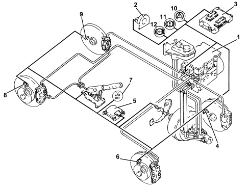
View of assembly
Specifications
The ABS control unit implements the ABS and EBD functions.The ABS control unit is connected to the front wiring, the system cable loom is incorporated with the engine compartment cable loom.| The pin out of the ABS control unit with EBD is different from control units with ASR and VDC functions. |
Composition
The ABS consists of:- an electronic control unit integral with the hydraulic control unit- an electrohydraulic control unit that modulates braking pressure by means of eight solenoids, two for each wheel- four active sensors that detect the angular rotating speed of the wheels.- wiring with specific connectorOperation
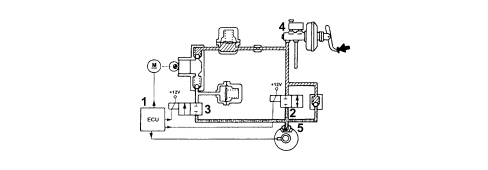
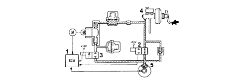
IntroductionThe electronic control unit processes signals from the active sensors and brake light control switch. It identifies the wheel or wheels with a tendency to lock (maximum slip between wheel and road surface) by means of the control unit software and modulates the brake fluid pressure selectiely for the front wheels and in tandem for the rear wheels (select-low function).The ABS modulates brake pressure in accordance with three basic stages:- pressure maintenance stage- pressure reduction stage- pressure increase stageIf operation is requested, the ABS stays active at speeds greater than 2.7 km/h. After that, it cuts out to allow the car to stop. After each key ON and when a speed of 6 km/h is exceeded, the control unit carries out an operation check on the solenoids and pump engine. The control unit also tests the sensors when a speed of 12 km/h is exceeded.Operating logicsPRESSURE INCREASE STAGE WITHOUT ABS OPERATIONWhen the brake pedal is pressed, the electronic control unit (1):- does not supply load solenoid (N.O.) (2)- does not supply discharge solenoid (N.C.) (3)The pressure generated by brake pump (4) therefore reaches brake calipers (5) without undergoing changes.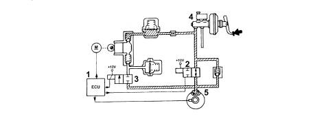
ASR TRACTION CONTROL/ADJUSTMENT DEVICES
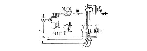
In addition to the ABS EBD system, the vehicle is also equipped with a system for controlling the stability of the vehicle VDC which includes the traction control system ASR.The VDC system, in particular, thanks to slewing sensors and steering wheel angle sensors, guarantees the monitoring of the dynamics of the entire vehicle thereby improving active safety.View of assembly
Specifications
Driving a vehicle in all conditions where the physical limits of grip and, consequently, stability may be reached can be a difficult task for the average driver therefore in order to further improve safe driving conditions an electronic system capable of assisting the driver with this difficult task is available.The systems currently employed to ensure safer driving in particular conditions are mainly the A.B.S. which controls braking and the T.C. and systems which control traction during acceleration through action on the brakes (T.C.) and traction/drive torque during acceleration and release through action on the brakes and on the engine control system motorized throttle (A.S.R./M.S.R.).The VDC system includes all the above listed functions ensuring optimum dynamic control of the vehicle with the addition of specific sensors:- steering angle sensor on the steering wheel- slewing/lateral acceleration sensor at the centre of gravity under the centre tunnel.
| To ensure the drive of the vehicle (drive wheels) with snow chains fitted or in particular road surface conditions (snow, ice, deep mud, sand or gravel) it is advisable to switch the A.S.R. off. |
Composition
The VDC system consists of:- an electro-hydraulic/electronic A.B.S. control unit (with an VD logic)- interface with the C-CAN line, resident in the ABS control unit for communication with the engine control unit, steering angle sensor and lateral acceleration sensor;- Magnetic-resistive type wheel speed sensors- steering angle sensor with C.A.N. interface (steering angle sensor)- slewing/lateral acceleration sensor in one piece integral with the CAN interface;- brake fluid pressure sensor incorporated in the A.B.S. control unit- ABS-EBD-VDC warning light in the instrument panel controlled via the dedicated serial line- A.S.R. off switch with a warning light in the buttonOperation
The VDC continuously recognizes a loss in grip for the wheels, both longitudinal and transverse, in all driving conditions from braking to acceleration in order to ensure the direction and the stability of the vehicle.The management of the VDC system is entrusted to the A.B.S. electronic control unit, integrated with a special electro-hydraulic control unit, that allows action on the braking system independently of the action of the user.The control unit processes the following signals:- steering wheel rotation angle- lateral acceleration and slewing- engine operating conditions:- wheel rpm- hydraulic braking system pressureand uses special algorithms in the electronic control unit software to obtain the figures for the dynamic control of the vehicle:- longitudinal and transverse sliding between the wheels and the road surface- axle drift.Using these figures the system interprets the effective dynamics of the vehicle; having identified all the critical conditions due to environmental factors (e.g. surface with poor grip) or any errors made by the user (e.g. panic situations) and with subsequent intervention on the brakes and the drive torque, the vehicle is restored to good driving conditions.The system interfaces with:- NCM for drive torque adjustment via the C-CAN line;- control panel via a serial line for warning light control.The system is combined with a power unit with a specific brake pump; in addition, the pipes between the brake pump and the A.B.S. control unit have a Titaflex insert because the diameter of the pipe (6mm) is larger than regular pipes (4 mm); this is designed to prevent adverse effects on the operation of the VDC at low brake fluid temperatures.There is a dedicated line (line K) for the diagnosis of the system.The VDC system switches on automatically when the vehicle is started up and cannot be switched off by the user; the button in the centre console only switches off the A.S.R. function and only when advisable.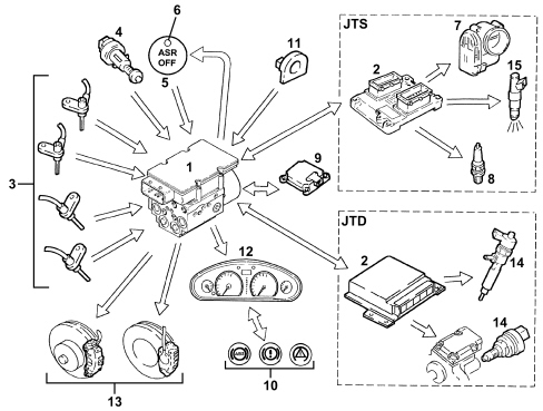
| ... DATA ERROR - CROPPED TEXT | Ошибка данных - Текст обрезан ... |
|---|