939010421 - 1016E10 SINGLE CYLINDER HEAD, REMOVED - OVERHAUL
| Tool | Description | Function | Validity |
|---|---|---|---|
| 1860470000 | Support | Overhaul cylinder head |


| The camshaft caps are numbered from 2 to 5, inlet side and from 6 to 9, exhaust side. The front cap, which is the same for both camshafts, is number 1. |
| The bolts securing the camshaft caps should be loosened in a spiral sequence, starting from the caps on the outside, in the following order: 5 - 2 - 4 - 3. |

| Mark the fitting position of the camshafts. |


| Tool | Description | Function | Validity |
|---|---|---|---|
| 1860804001 | Stand | Removing/refitting valves | 1.81.9 JTD 16V |

| Tool | Description | Function | Validity |
|---|---|---|---|
| 1860644001 | Lever | Removing/refitting valves | 1.81.9 JTD 16V |
| Tool | Description | Function | Validity |
|---|---|---|---|
| 1870881000 | Chamber | Removing/refitting valves | 1.8 |

| Tool | Description | Function | Validity |
|---|---|---|---|
| 1870894000 | Extractor | Valve guide oil seal extraction | 1.81.9 JTD 8V |

| Measurement | Value | Validity | ||
|---|---|---|---|---|
| Cylinder head lower surface flatness | 0.05 mm | 1.8 | ||
| Measurement | Value | Validity |
|---|---|---|
| Inlet valve seat width (mm) | 1.0 ÷ 1.4 | 1.8 |
| Measurement | Value | Validity |
|---|---|---|
| Exhaust valve seat width (mm) | 1.8 |
| Measurement | Value | Validity |
|---|---|---|
| Valve seat angle | 90° 30’ | 1.8 |
| Measurement | Value | Validity |
|---|---|---|
| Inlet valve head diameter (mm) | 30.7 ÷ 30.8 | 1.8 |
| Measurement | Value | Validity |
|---|---|---|
| Exhaust valve head diameter (mm) | 27.1 ÷ 27.2 | 1.8 |
| Measurement | Value | Validity |
|---|---|---|
| Valve head angle | 90° 40’ | 1.8 |
| Measurement | Value | Validity |
|---|---|---|
| Inlet valve stem diameter (mm) | 4.955 ÷ 4.970 | 1.8 |
| Measurement | Value | Validity |
|---|---|---|
| Exhaust valve stem diameter (mm) | 4.935 ÷ 4.950 | 1.8 |
| Measurement | Value | Validity |
|---|---|---|
| Valve stem diameter oversizes (mm) | 0.075/0.150 | 1.8 |

| Tool | Description | Function | Validity |
|---|---|---|---|
| 1860804001 | Stand | Removing/refitting valves | 1.81.9 JTD 16V |
| Tool | Description | Function | Validity |
|---|---|---|---|
| 1870894000 | Extractor | Valve guide oil seal extraction | 1.81.9 JTD 8V |
| Tool | Description | Function | Validity |
|---|---|---|---|
| 1860644001 | Lever | Removing/refitting valves | 1.81.9 JTD 16V |
| Tool | Description | Function | Validity |
|---|---|---|---|
| 1870881000 | Chamber | Removing/refitting valves | 1.8 |
| Tool | Description | Function | Validity |
|---|---|---|---|
| 1860804001 | Stand | Removing/refitting valves | 1.81.9 JTD 16V |
| Component | Fastening | dia | Value (daNm) | Validity |
|---|---|---|---|---|
| Camshaft caps | Bolt | - | 0.8 | 1.8 |
| Measurement | Value | Validity |
|---|---|---|
| Inlet valve clearance in closed position (mm) | 0.21 ÷ 0.29 | 1.8 |
| Measurement | Value | Validity |
|---|---|---|
| Exhaust valve clearance in closed position (mm) | 0.27 ÷ 0.35 | 1.8 |

| The tappet cups are graded according to size and therefore the Spare Parts list should be consulted for selecting the new cup to be fitted. The code is on the cup crown. |
| Tool | Description | Function | Validity |
|---|---|---|---|
| 2000012000 | Template | Camshaft timing | 1.8 |

| Tool | Description | Function | Validity |
|---|---|---|---|
| 2000012100 | Template | Camshaft timing | 1.8 |
| Fit the inlet side template first and then the exhaust side one. |
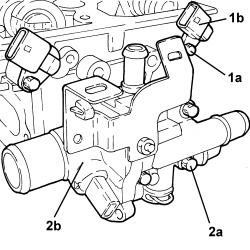
| When the templates are fitted, check that:- the reference (a) on the exhaust-side pulley is aligned with the reference (b) on the corresponding timing template;- the pin (c) on the intake-side pulley is in the position illustrated in the diagram in relation to the reference (d) on the corresponding timing template. |
| Component | Fastening | dia | Value (daNm) | Validity |
|---|---|---|---|---|
| Variable valve timing actuator | Bolt (to be replaced) | - | 6.5 + 120° + 15° | 1.8 |

| Component | Fastening | dia | Value (daNm) | Validity |
|---|---|---|---|---|
| Timing sensor | Bolt | M6 | 0.6 ÷ 0.8 | 1.8 |
| Component | Fastening | dia | Value (daNm) | Validity |
|---|---|---|---|---|
| Spark plugs | - | - | 2.5 | 1.8 |