939003514 - GENERAL REMARKS - GEARBOX (C.A.E.)
DESCRIPTION
The AISIN AF 40-6 is a 6-speed automatic transmission used on the 1.9 JTD 16V and 2.4 JTD 20V engine versions.GENERAL SPECIFICATIONS
- Type 6-speed automatic transmission- Engine: 1.9 JTD 16V and 2.4 JTD 20V- Architecture: 3 clutches, 2 brakes, 1 free wheel, 2 epicyclic trains- Hydraulic: 4 linear solenoids, 2 on/off solenoids- Electronic: Neutral Start Switch and control unit built in, internal wiring and speed sensors| NAME | AF 40-6 | |||
|---|---|---|---|---|
| VEHICLE | CROMA | |||
| ENGINE TYPES | 1.9 JTD 16V | 2.4 JTD 20V | ||
| TRANSMISSION RATIO | 1 | 4.148 | ||
| 2 | 2.370 | |||
| 3 | 1.556 | |||
| 4 | 1.155 | |||
| 5 | 0.859 | |||
| 6 | 0.686 | |||
| R | 3.394 | |||
| Idler shaft | 0.836 | |||
| Differential | 3.188 | |||
| BRAKES AND CLUTCHES | CLUTCHES | C1 | 1 flange, 6 discs, 6 plates | 1 flange, 7 discs, 7 plates |
| C2 | 1 flange, 3 discs, 3 plates | 1 flange, 4 discs, 4 plates | ||
| C3 | 1 flange, 4 discs, 4 plates | |||
| BRAKES | B1 | Band | ||
| B2 | 2 flanges, 6 discs, 5 plates | 2 flanges, 6 discs, 5 plates | ||
| One-Way | F1 | Roller type | ||
| SOLENOIDS | Shift solenoid | n. 2 | ||
| Linear | n. 6 | |||
| LINE PRESSURE [KPa] | MINIMUM | D | 372 - 414 | |
| R | 575 - 665 | |||
| STALL | D | 1350 - 1460 | ||
| R | 1905 - 2125 | |||
FUNCTION
Neutral control
When the vehicle stops with the lever set to "D", the clutches are automatically released and the transmission changes to neutral. In this way, the torque converter is not put under stress, there are fewer vibrations and fuel consumption is minimal.On rough roads or on hills, the function does not activate. On hills, the transmission remains engaged to assure a hill holder effect.Reversing control
When the gearlever is shifted from "N" to "R", reverse is not engaged if vehicle speed exceeds 11 km/h.Adaptivity
| MODE | DESCRIPTION |
|---|---|
| ADAPTIVITY | Used during normal driving The sports or economy modes are selected automatically depending on driving conditions |
| SPORT | In this mode, the speed passage points and lock-up operation are higher because the rpm is higher |
| WINTER/LOW GRIP | In the event of ice, snow and low grip in general, the car sets off in third gear to prevent the front wheels slipping |
| TIP | When the lever is moved from “D” to “+/-”, the driver can select the speed passage point sequentially. In any case, the control unit changes the ratio automatically to prevent over-revving or viceversa to prevent juddering because the engine speed is too low. |
| HIGH TEMPERATURE | If the transmission fluid temperature is too high, the control unit advances lock-up intervention to prevent the torque converter slipping excessively and thus lowering the temperature. |
| HEATING | Conversely, in this case converter slip is promoted to heat the fluid. |
| GRADIENTS | A gradient is automatically detected by a control unit algorithm based on rpm increase. The speed passage points are increased. |
| DESCENT | Conversely, on a descent, the system uses certain features to prevent excessive use of the brakes (lock-up etc.) |
| FAST ON | This control computes the driver''s desire for performance expressed by pressure on the accelerator pedal, and adjusts the speed passage points accordingly. |
| BRAKE ASSISTANCE | Conversely, in this case the engine brake is used to help the driver during acceleration (detected via the accelerator pedal) |
COMPONENTS
Control unit

| 1 | Key switch signal |
| 2 | N.C. |
| 3 | N.C. |
| 4 | K line |
| 5 | Steering lock signal |
| 6 | CAN L |
| 7 | CAN H |
| 8 | CAN H |
| 9 | Earth |
| 10 | N.C. |
| 11 | Fuel system |
| 12 | N.C. |
| 13 | Reversing light relay |
| 14 | CAN L |
| 15 | N.C. |
| 16 | N.C. |
| SIGNAL | I/O | TRANSMISSION TYPE |
|---|---|---|
| key status | I | CAN |
| System warning light | O | CAN |
| Transmission fluid max temperature warning light | O | CAN |
| Speed engaged display | O | CAN |
| Gear selection | I | CAN |
| System diagnosis | I/O | K |
| Vehicle speed | I | CAN |
| Brake pedal pressed for recovery (brake light contact) | I | CAN |
| Driver''s front door status | I | CAN |
| Horn activation | O | CAN |
| Start-up enablement to NBS | O | on/off @GND |
| Reversing light control | O | on/off @+15 |
| Engine coolant temperature | I | CAN |
| Engine torque change request | O | CAN |
| MIL warning light activation request | O | CAN |
Wiring
The wiring is located inside the gearbox, it is connected to the inside of the valve body:- to the speed sensors- to the fluid temperature sensor- to the solenoidsThe wiring is connected to the transmission control unit with an Aisin pin-to-pin connector.
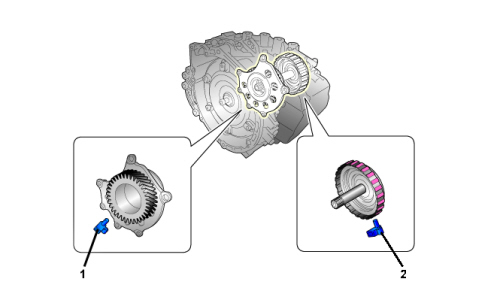
Solenoid unit
The valve unit, via solenoids activated by signals from the control unit, supplies hydraulic pressure produced by the oil pump to the brakes, clutches and lock-up. Part of the fluid is also sent to lubricate the mechanical components.
Solenoids
The linear solenoids shown in the figure control the hydraulic pressure of almost all the brakes/clutches


Sensors
Lever position sensor (nsw)The position sensor is Hall effect and is built into the control unit. It sends the gear lever position.

| Temperature (°C) | Resistance (kO) |
|---|---|
| 10 | 5.62-7.31 |
| 25 | 3.5 |
| 110 | 0.22-0.27 |