125001405 - 4130A10 POWER STEERING BOX - R+R - CHECK TOW-IN IF NECESSARY SEPARATELY - INCLUDES BLEEDING
| The bolt is pretreated and cannot therefore be refitted. |

 | Name | Country |
|---|---|---|
| 1c | Extractor | 1.821.169.000 |


 | Fastening | Component | Ø | Value(daNm) |
|---|---|---|---|---|
| 1b | Nut | FRONT ANTI-ROLL BAR JOINTS | M10 | (Front shock absorber fork side) 4.1 ÷ 5.0 |

| Fastening | Component | Ø | Value(daNm) |
|---|---|---|---|---|
| 1 | Side bolt | ENGINE OR ROD ANCHORAGE BEAM | M12 | (Bodyshell side) 10.8 ÷ 13.2 |
| Fastening | Component | Ø | Value(daNm) |
|---|---|---|---|---|
| 2 | Rear bolt | ENGINE OR ROD ANCHORAGE BEAM | M10 | (Bodyshell side) 8.1 ÷ 9.9 |
| Fastening | Component | Ø | Value(daNm) |
|---|---|---|---|---|
| 2 | Rear bolt | ENGINE OR ROD ANCHORAGE BEAM | M12 | (Bodyshell side) 10.8 ÷ 13.2 |
| Fastening | Component | Ø | Value(daNm) |
|---|---|---|---|---|
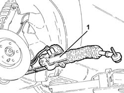
| 3 | Bolt | POWER STEERING BOX | M14 | (Front suspension crossmember side) 11.7 ÷ 14.3 |

| Fastening | Component | Ø | Value(daNm) |
|---|---|---|---|---|
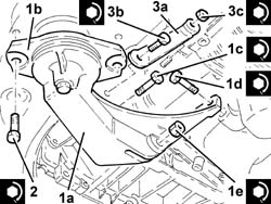
| 1c | Bolt | POWER UNIT RIGID REAR MOUNT | M12 | (Gearbox side) 7.2 ÷ 8.8 |
| Fastening | Component | Ø | Value(daNm) |
|---|---|---|---|---|
| 1d | Bolt | POWER UNIT RIGID REAR MOUNT | M12 | (Crankcase sump side) 6.8 ÷ 8.3 |
| Fastening | Component | Ø | Value(daNm) |
|---|---|---|---|---|
| 1e | Nut | POWER UNIT RIGID REAR MOUNT | M12 | (Gearbox side) 7.2 ÷ 8.8 |
| Fastening | Component | Ø | Value(daNm) |
|---|---|---|---|---|
| 2 | Bolt | INTERM RUBBER MOUNT | M8 | (Front suspension crossmember side) 3.2 ÷ 3.9 |
| Fastening | Component | Ø | Value(daNm) |
|---|---|---|---|---|
| 3b | Bolt | POWER UNIT RIGID REAR SUPPORT REINFORCEMENT ROD.... | M12 |
| Fastening | Component | Ø | Value(daNm) |
|---|---|---|---|---|
| 3c | - | - | - | - |
| Fastening | Component | Ø | Value(daNm) |
|---|---|---|---|---|
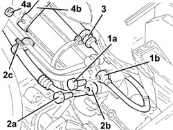
| 3b | Connector | PIPE FROM POWER STEERING BOX/EXCHANGER | M12 | (Power steering box side) 2.7 ÷ 3.3 |
| Fastening | Component | Ø | Value(daNm) |
|---|---|---|---|---|
| 4b | Connector | PIPE BTWN PUMP + POWER STEERING BOX | M14 | (Power assisted steering box side) 3.6 ÷ 4.4 |

| Fastening | Component | Ø | Value(daNm) |
|---|---|---|---|---|
| 1b | Nut | ADJUSTABLE STEERING LINKS | M10 | (Front steering knuckle side) 3.2 ÷ 3.9 |

| Fastening | Component | Ø | Value(daNm) |
|---|---|---|---|---|
| 1b | Bolt | STEERING SHAFTS | M8 | (Power assisted steering box pinion side) 2.3 ÷ 2.8 |
