2753382 - 1024A10 crank shaft - r + r with engine removed - check main and connecting rod bearingand replace if necessary
 | Name | Country |
|---|---|---|
| 1 | Counter-torque | 1.860.846.000 |

| Name | Country |
|---|---|---|
| 1a | Counter-torque | 1.870.744.000 |
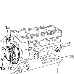
| Work with flywheel retainer 1860846000 fitted. |


| Name | Country |
|---|---|---|
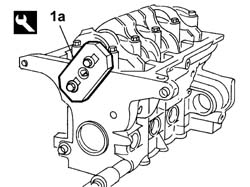
| 1a | Flange | 1.860.815.000 |
| Name | Country |
|---|---|---|
| - | Flange | 1.860.815.000 |

 | Measurement | Value | |
|---|---|---|---|
| 1 | End float (mm) | 0.055 ÷ 0.265 |

| The central main bearing halves incorporate crankshaft thrust half-rings. |

| Measurement | Value | |
|---|---|---|---|
| - | Main bearing journal diameter (mm) | Category B | 47.988 - 47.994 |
| Category C | 47.982 - 47.988 | ||
| Classe A | 47.994 - 48.000 | ||
| The shaft has undergone a nitriding treatment; therefore if it needs regrinding it should undergo the nitriding treatment again and the dimensions should then be checked. |
| Measurement | Value | |
|---|---|---|---|
| - | Crankpin undersize (mm) | 0.254 / 0.508 |
| Measurement | Value | |
|---|---|---|---|
| - | Crankpin diameter (mm) | Category B | 41.995 - 42.001 |
| Category C | 41.988 - 41.995 | ||
| Classe A | 42.001 - 42.008 | ||
| The shaft has undergone a nitriding treatment; therefore if it needs regrinding it should undergo the nitriding treatment again and the dimensions should then be checked. |
| Measurement | Value | |
|---|---|---|---|
| - | Crankpin undersize (mm) | 0.254 - 0.508 |

 | Fastening | Component | Ø | Value(daNm) |
|---|---|---|---|---|
| 1c | Bolt | MAIN BEARING CAPS | M10 x 1.25 | 2 + 90° |
| Name | Country |
|---|---|---|
| 1d | Protractor | 1.860.942.000 |
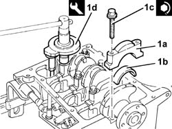
| Check one pin at a time without turning the crankshaft. |
| Measurement | Value | |
|---|---|---|---|
| - | Clearance between crankshaft bearings - big end bearings (mm) | 0.025 - 0.049 |

| Name | Country |
|---|---|---|
| - | Flange | 1.860.815.000 |

| Name | Country |
|---|---|---|
| 1b | Fitting tool | 1.860.700.000 |


| The connecting rod caps are fitted so that the number stamped on them is facing the same side as the one stamped on the big end (inlet side). |
| Fastening | Component | Ø | Value(daNm) |
|---|---|---|---|---|
| 1c | Bolt | CONNECTING ROD CAP FASTENERS | M8 x 1 | 4.1 |

| Check the one connecting rod pin at a time without rotating the crankshaft. |
| Measurement | Value | |
|---|---|---|---|
| - | Clearance between big end bearings-Crankpins (mm) | 0.024 - 0.062 |

| Name | Country |
|---|---|---|
| - | Flange | 1.860.815.000 |
| Fastening | Component | Ø | Value(daNm) |
|---|---|---|---|---|
| 2b | Bolt | ENGINE OIL PUMP | M6 x 1 | 1 |

| Name | Country |
|---|---|---|
| 1b | Fitting tool | 1.860.903.000 |

| Fastening | Component | Ø | Value(daNm) |
|---|---|---|---|---|
| - | Bolt | FLYWHEEL SIDE COVER | M6 x 1 | 1 |

| Name | Country |
|---|---|---|
| 1b | Grip | 1.860.879.000 |
| Name | Country |
|---|---|---|
| 1c | Fitting tool | 1.860.881.000 |

| Name | Country |
|---|---|---|
| 1 | Counter-torque | 1.860.846.000 |
| Fastening | Component | Ø | Value(daNm) |
|---|---|---|---|---|
| - | Bolt | FLYWHEEL | M8 x 1.25 | 4.4 |

| Name | Country |
|---|---|---|
| 2 | Counter-torque | 1.870.744.000 |
| Fastening | Component | Ø | Value(daNm) |
|---|---|---|---|---|
| - | Bolt | TOOTHED DRIVE PULLEY | M11 x 1 | 2 + 90° |

| Name | Country |
|---|---|---|
| 1 | Counter-torque | 1.860.846.000 |
| Fastening | Component | Ø | Value(daNm) |
|---|---|---|---|---|
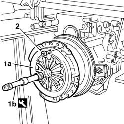
| 2c | Bolt | FLYWHEEL | M8 x 1.25 | 4.4 |

| Name | Country |
|---|---|---|
| 1b | Clutch centering | 1.870.418.000 |
| Ensure a perfect join between start and end section. |
 | Type | Component | Name | Qty. |
|---|---|---|---|---|
| 1 | Sealant | CRANK CASE PLUGS | Loktite 270 | - |
| When fitting the crankcase sump, avoid major sideways movements which may remove the sealant. |
| Fastening | Component | Ø | Value(daNm) |
|---|---|---|---|---|
| 2b | Bolt | OIL SUMP | M6 | 1 |
| Fastening | Component | Ø | Value(daNm) |
|---|---|---|---|---|
| 2c | Nut | OIL SUMP | M6 | 0.7 |

| ASTADUR type cylinder head gaskets
are fitted. These gaskets are made from a special material designed
to undergo polymerization during the use of the engine. This means
that they harden considerably during use. In order for the polymerization process to take place it is necessary:
|
| Follow the order shown in the diagram for each tightening sequence. |
| Fastening | Component | Ø | Value(daNm) |
|---|---|---|---|---|
| 1a | Bolt | CYLINDER HEAD | M9 x 1.25 | 3 + 90° + 90° |
| Name | Country |
|---|---|---|
| 1b | Protractor | 1.860.942.000 |

| Fastening | Component | Ø | Value(daNm) |
|---|---|---|---|---|
| - | Bolt | CAM COVER | M6 x 1 | 1 |

| The weight for the tool (1b) should have the knurled part removed and should be positioned 65 mm away on the millimetric rod. The millimetric rod should be placed in a horizontal position acting on the tool joint. |
| Name | Country |
|---|---|---|
| 1a | Belt tensioner | 1.860.745.300 |
| Name | Country |
|---|---|---|
| 1b | Belt tensioner | 1.860.745.100 |
| During this stage the millimetric rod may move away from the horizontal position; if this is the case, adjust the joint on the tool and repeat the operation. |
| Fastening | Component | Ø | Value(daNm) |
|---|---|---|---|---|
| 2 | Nut | MOBILE TIMING TENSIONER | M8 x 1.25 | 2.8 |

| Fastening | Component | Ø | Value(daNm) |
|---|---|---|---|---|
| - | Bolt | CRANKSHAFT PULLEY | M8 x 1.25 | 2.2 |
 | Name | Connector |
|---|---|---|
| - | Throttle position sensor | K56 |
| Name | Connector |
|---|---|---|
| - | Idle actuator | N74 |
| Name | Connector |
|---|---|---|
| - | Fuel vapour recovery solenoid | L10 |
| Name | Connector |
|---|---|---|
| - | Engine coolant temperature sensor/sender unit | K36 |
| Name | Connector |
|---|---|---|
| - | Injector | N70 |
| Name | Connector |
|---|---|---|
| - | Battery earth on engine | C2 |
| Name | Connector |
|---|---|---|
| - | Detonation sensor | K50 |
| Name | Connector |
|---|---|---|
| - | Engine oil pressure sensor | K28 |
| Name | Connector |
|---|---|---|
| - | Integrated air temperature sensor | K43 |
| Name | Connector |
|---|---|---|
| - | Rpm sensor | K46 |