194000444 - 2110B20 MANUAL GEARBOX (5-6SPEED) WITH DIFFERENTIAL - DISMANTLING AND REASSEMBLY - WASH AND CHECK PARTS - REPLACE SYNCHRONISERS AND INTERNAL CONTROLS IF NECESSARY
| Two mechanics are needed for this operation. |
| Tool | Description | Function | Validity |
|---|---|---|---|
| 1871000000 | Overhaul stand | Manual gearbox overhaul | 1.82.2 |
| Tool | Description | Function | Validity |
|---|---|---|---|
| 1871001014 | Support | Positioning gearbox and differential on overhaul stand | 2.2 |

| Replace the bush after disassembly. |


| The intermediate shaft sealing plug and the oil deflector should always be replaced. |

| Tool | Description | Function | Validity |
|---|---|---|---|
| 1870718000 | Blade | Cut sealant |

| Tool | Description | Function | Validity |
|---|---|---|---|
| 1870853000 | Bush | Main shaft counter-torque | 2.2 |
| Always replace the intermediate shaft bolt; its threads are micro-encapsulated. |

| Tool | Description | Function | Validity |
|---|---|---|---|
| 1870853000 | Bush | Main shaft counter-torque | 2.2 |
| Always replace the shaft bolts. |


| Tool | Description | Function | Validity |
|---|---|---|---|
| 1870844000 | Extractor/Fitting tool | Tool for main and layshaft bearings | 2.2 |


| Tool | Description | Function | Validity |
|---|---|---|---|
| 1870741000 | Bush | Locking main/layshaft synchronizers | 2.2 |
| Tool | Description | Function | Validity |
|---|---|---|---|
| 1878082000 | Bush | Locking main shaft synchronizers/half-casing opening tool | 2.2 |


| Tool | Description | Function | Validity |
|---|---|---|---|
| 1870007000 | Grip | Grip for tool for extracting bearing/fitting main shaft oil seal/fitting differential bearing race |
| Tool | Description | Function | Validity |
|---|---|---|---|
| 1860981000 | Extractor | Adaptor for extracting bearing | 2.2 |

| Tool | Description | Function | Validity |
|---|---|---|---|
| 1870007000 | Grip | Grip for tool for extracting bearing/fitting main shaft oil seal/fitting differential bearing race |
| Tool | Description | Function | Validity |
|---|---|---|---|
| 1870629000 | Extractor | Adaptor for extracting bearing | 2.2 |


| Tool | Description | Function | Validity |
|---|---|---|---|
| 1860837000 | Plate | Plate for support in the press |
| Tool | Description | Function | Validity |
|---|---|---|---|
| 1870677000 | Half-rings | Plate for reaction in the press | 2.2 |
| Mark the parts removed to indicate their direction and installation direction upon refitting. Pay particular attention to the synchroniser unit to ensure that the round mark on the sleeve is located on the 3rd speed side. |
| Tool | Description | Function | Validity |
|---|---|---|---|
| 1875088000 | Extractor/Drift | Extractor | 2.2 |
| Tool | Description | Function | Validity |
|---|---|---|---|
| 1870418000 | Insert | Insert for fitting tool | 2.2 |

| Tool | Description | Function | Validity |
|---|---|---|---|
| 1860837000 | Plate | Plate for support in the press |
| Tool | Description | Function | Validity |
|---|---|---|---|
| 1870418000 | Insert | Insert for fitting tool | 2.2 |
| The 5th speed drive gear should be replaced after removal. |

| Tool | Description | Function | Validity |
|---|---|---|---|
| 1860837000 | Plate | Plate for support in the press |
| Tool | Description | Function | Validity |
|---|---|---|---|
| 1846017000 | Half-rings | Half-rings for reaction in the press |

| Tool | Description | Function | Validity |
|---|---|---|---|
| 1860837000 | Plate | Plate for support in the press |
| Mark the parts removed to indicate the installation position and direction upon refitting. Pay particular attention to the synchronisation unit. |


| Tool | Description | Function | Validity |
|---|---|---|---|
| 1860837000 | Plate | Plate for support in the press |
| Tool | Description | Function | Validity |
|---|---|---|---|
| 1870675000 | Half-rings | Half-rings for reaction in the press | 2.2 |
| Tool | Description | Function | Validity |
|---|---|---|---|
| 1875088000 | Extractor/Drift | Extractor | 2.2 |

| Tool | Description | Function | Validity |
|---|---|---|---|
| 1870677000 | Half-rings | Plate for reaction in the press | 2.2 |
| Tool | Description | Function | Validity |
|---|---|---|---|
| 1860837000 | Plate | Plate for support in the press |
| Tool | Description | Function | Validity |
|---|---|---|---|
| 1875088000 | Extractor/Drift | Extractor | 2.2 |
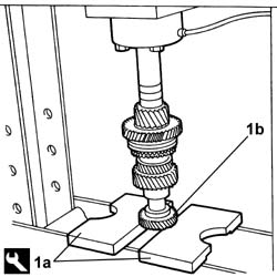
| To remove the 3rd speed driven gear, apply a load of at least 11 tons. |
| The 3rd and 4th speed driven gear is guaranteed for two removals and you should therefore punch the number of removals undergone on the gear. Replace after the second removal. |

| Tool | Description | Function | Validity |
|---|---|---|---|
| 1860837000 | Plate | Plate for support in the press |
| Mark the parts removed to indicate their direction and installation direction upon refitting. Pay particular attention on the synchronisation unit to ensure that the double round mark on the sleeve is located on the reverse side. |

| Tool | Description | Function | Validity |
|---|---|---|---|
| 1860837000 | Plate | Plate for support in the press |
| Tool | Description | Function | Validity |
|---|---|---|---|
| 1870152000 | Fitting tool | Tool for fitting bush/layshaft 3rd speed driven gear | 2.2 |

| Tool | Description | Function | Validity |
|---|---|---|---|
| 1860837000 | Plate | Plate for support in the press |
| Tool | Description | Function | Validity |
|---|---|---|---|
| 1870152000 | Fitting tool | Tool for fitting bush/layshaft 3rd speed driven gear | 2.2 |

| Tool | Description | Function | Validity |
|---|---|---|---|
| 1860837000 | Plate | Plate for support in the press |
| Tool | Description | Function | Validity |
|---|---|---|---|
| 1860837000 | Plate | Plate for support in the press |

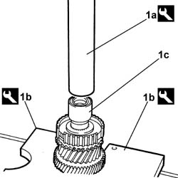
| Check that the dual synchronizer teeth are properly fitted in the grooves in the gear. |

| Tool | Description | Function | Validity |
|---|---|---|---|
| 1860837000 | Plate | Plate for support in the press |
| Check that the synchronizers rotate freely without interference. |

| Tool | Description | Function | Validity |
|---|---|---|---|
| 1860837000 | Plate | Plate for support in the press |


| Tool | Description | Function | Validity |
|---|---|---|---|
| 1860837000 | Plate | Plate for support in the press |
| After press-fitting the hub, check that the 4th speed drive gear and the synchroniser ring turn freely without interference. |

| Tool | Description | Function | Validity |
|---|---|---|---|
| 1860837000 | Plate | Plate for support in the press |
| Tool | Description | Function | Validity |
|---|---|---|---|
| 1870741000 | Bush | Locking main/layshaft synchronizers | 2.2 |
| The synchronisation springs, balls and pads are not supplied individually. If lost, replace the synchroniser assembly. |


| Tool | Description | Function | Validity |
|---|---|---|---|
| 1870741000 | Bush | Locking main/layshaft synchronizers | 2.2 |
| Tool | Description | Function | Validity |
|---|---|---|---|
| 1870844000 | Extractor/Fitting tool | Tool for main and layshaft bearings | 2.2 |
| The bearing retaining rings must not be removed. If necessary to replace the bearing retaining rings, fit before fitting the bearings into their seats on the gearbox. |


| Tool | Description | Function | Validity |
|---|---|---|---|
| 1878082000 | Bush | Locking main shaft synchronizers/half-casing opening tool | 2.2 |


| The sealant strip must be 1 mm wide. |
| Whenver the lever locating bolt is removed, a new one must be fitted. |
| Component | Fastening | dia | Value (daNm) | Validity |
|---|---|---|---|---|
| Gear selection and engagement assembly | Upper bolts | - | (gearbox side) 2.5 | 2.2 |

| Do not use LOCTITE in area "A" because it could enter the transmission and block the lubrication holes to cause premature failure of the roller bearings. |

| Component | Fastening | dia | Value (daNm) | Validity |
|---|---|---|---|---|
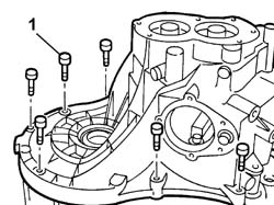
| Manual gearbox/diff casing | Inner bolts | - | 2.8 | 2.2 |

| Tool | Description | Function | Validity |
|---|---|---|---|
| 1870853000 | Bush | Main shaft counter-torque | 2.2 |
| Component | Fastening | dia | Value (daNm) | Validity |
|---|---|---|---|---|
| Manual gearbox/differential main and layshafts | Bolt | - | 10.0 | 2.2 |
| Component | Fastening | dia | Value (daNm) | Validity |
|---|---|---|---|---|
| Manual gearbox/differential intermediate shaft | Bolt | - | 10.0 | 2.2 |

| The sealant strip must be 1 mm wide. |
| When applying the sealant, avoid spreading the area of contact with the underlying oil pipe. |
| Do not use an excessive amount of LOCTITE ibecause it could enter the transmission and block the lubrication holes to cause premature failure of the roller bearings. |
| Component | Fastening | dia | Value (daNm) | Validity |
|---|---|---|---|---|
| Gearbox rear cover | Bolt | - | (gearbox casing side) 2.5 | 2.2 |

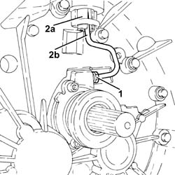
| If a new hydraulic clutch actuator is fitted, remove the device used for locking during transport (red bracket). |
| Component | Fastening | dia | Value (daNm) | Validity |
|---|---|---|---|---|
| Clutch hydraulic actuator | Bolt | - | (gearbox side) 0.6 - 1.2 |

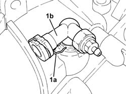
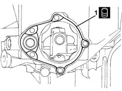
| The dog on the bush must align with the seat on the gear casing. |
| Check the o-ring on the rigid pipe and replace if necessary. |
| Component | Fastening | dia | Value (daNm) | Validity |
|---|---|---|---|---|
| Clutch hydraulic actuator rigid pipe | Connector | - | (actuator side) |
| Two mechanics are needed for this operation. |
| Tool | Description | Function | Validity |
|---|---|---|---|
| 1871000000 | Overhaul stand | Manual gearbox overhaul | 1.82.2 |
| Tool | Description | Function | Validity |
|---|---|---|---|
| 1871001014 | Support | Positioning gearbox and differential on overhaul stand | 2.2 |