194000248 - 1016C10 SINGLE CYLINDER HEAD - R.R. AND REPLACE GASKET
| Collect the coolant in a suitable container. |


| Description | Connector | |
|---|---|---|
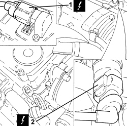
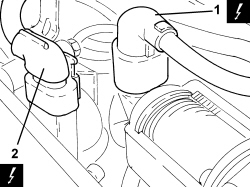
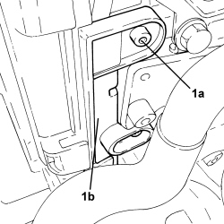
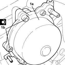
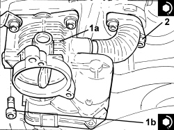
| 1 | Integrated throttle casing actuator | See N075 INTEGRATED THROTTLE CASING ACTUATOR |
| Description | Connector | |
|---|---|---|
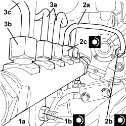
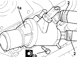
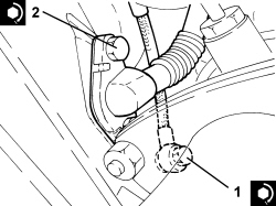
| 2 | Fuel pressure sensor | See K083 FUEL PRESSURE SENSOR |
| Description | Connector | |
|---|---|---|
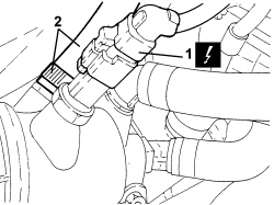
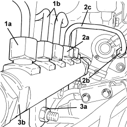
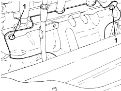
| 1 | Engine coolant temperature sensor/sender unit | See K036 ENGINE COOLANT TEMPERATURE SENSOR/SENDER UNIT |

| Description | Connector | |
|---|---|---|
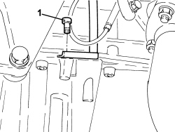
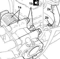
| 1 | E.G.R. solenoid valve | See L030 EGR SOLENOID VALVE |
| Description | Connector | |
|---|---|---|
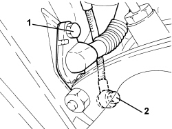
| 2 | Air pressure - temperature sensor | See K044 AIR PRESSURE - TEMPERATURE SENSOR |
| Description | Connector | |
|---|---|---|
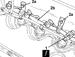
| 1 | Injector | See N070 INJECTOR |
| Description | Connector | |
|---|---|---|
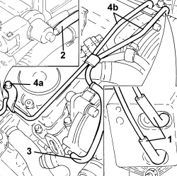
| 2 | Pressure regulator on pressure pump | See N077 FUEL PRESSURE REGULATOR |
| Description | Connector | |
|---|---|---|
| 3 | Fuel pressure regulator on rail | See N087 FUEL PRESSURE REGULATOR ON RAIL |


| Tool | Description | Function | Validity |
|---|---|---|---|
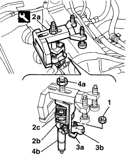
| 1870739000 | Extractor | Removing injectors | 1.9 JTD 8V1.9 JTD 16V |


| Description | Connector | |
|---|---|---|
| 2 | Heater plugs | See A040 HEATER PLUGS |

| If it has not been necessary to level the cylinder head, use a new cylinder head gasket of the same thickness as the old gasket. If the cylinder head required levelling, calculate the thickness of the new cylinder head to be used (see operation 1004E20). |
| Component | Fastening | dia | Value (daNm) | Validity |
|---|---|---|---|---|
| Cylinder head | Bolt | M12 | (engine crankcase side) 6.2 - 6.8 + 90° + 90° + 90° | 1.9 JTD 8v |
| Tool | Description | Function | Validity |
|---|---|---|---|
| 1860942000 | Torque wrench | Tighten bolts to torque plus angle |
| Component | Fastening | dia | Value (daNm) | Validity |
|---|---|---|---|---|
| Pressure pump mounting | Bolt | M10 | (cylinder head side) 4.5 - 5.5 | 1.9 JTD 8v |
| Component | Fastening | dia | Value (daNm) | Validity |
|---|---|---|---|---|
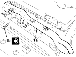
| Tappet cover | Bolt | M6 | (cylinder head side) 0.8 - 1.0 | 1.9 JTD 8v |
| Component | Fastening | dia | Value (daNm) | Validity |
|---|---|---|---|---|
| E.G.R. system solenoid valve | Bolt | M8 | (intake manifold side) 2.3 - 2.8 | 1.9 JTD 8v |
| Component | Fastening | dia | Value (daNm) | Validity |
|---|---|---|---|---|
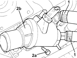
| Thermostat | Bolt | M8 | (cylinder head side) 2.3 - 2.8 | 1.9 JTD 8v |
| Component | Fastening | dia | Value (daNm) | Validity |
|---|---|---|---|---|
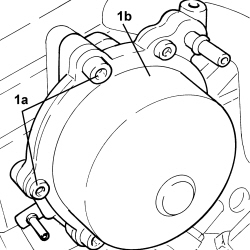
| Vacuum unit | Bolt | M8 | (cylinder head side) 2.7 - 3.3 | 1.9 JTD 8v |
| Component | Fastening | dia | Value (daNm) | Validity |
|---|---|---|---|---|
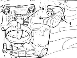
| Throttle body | Bolt | - | (intake manifold side) | 1.9 JTD 8v |
| Component | Fastening | dia | Value (daNm) | Validity |
|---|---|---|---|---|
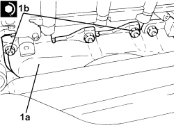
| Turbocharger and exhaust manifold assembly | Nut | M8 | (cylinder head side) 2.2 - 2.7 | 1.9 JTD 8v |
| Component | Fastening | dia | Value (daNm) | Validity |
|---|---|---|---|---|
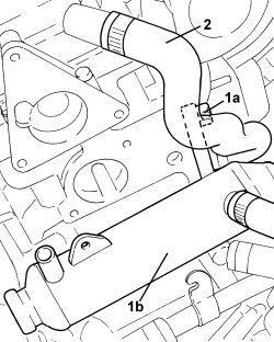
| Exhaust gas/water heat exchanger for E.G.R. system | Bolt | M8 | (exhaust manifold side) 2.3 - 2.8 | 1.9 JTD 8v |
| Component | Fastening | dia | Value (daNm) | Validity |
|---|---|---|---|---|
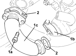
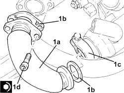
| Intermediate exhaust pipe with flexible section | Nut | M8 | (catalytic converter side) 2.2 - 2.6 | 1.9 JTD 16v1.9 JTD 8v2.4 JTD 20v |

| Component | Fastening | dia | Value (daNm) | Validity |
|---|---|---|---|---|
| Engine oil supply pipe to turbocharger | Connector | M12 | (engine crankcase side) 2.2 - 2.7 | 1.9 JTD 16v1.9 JTD 8v |
| Component | Fastening | dia | Value (daNm) | Validity |
|---|---|---|---|---|
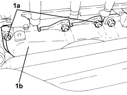
| Engine oil supply pipe from turbocharger | Bolt | M8 | (engine crankcase side) 2.2 - 2.7 | 1.9 JTD 16v1.9 JTD 8v |
| Component | Fastening | dia | Value (daNm) | Validity |
|---|---|---|---|---|
| Water pump rigid inlet pipe | Bolt | M6 | (cylinder head side) 0.8 - 1.0 | 1.9 JTD 16v1.9 JTD 8v |
| Component | Fastening | dia | Value (daNm) | Validity |
|---|---|---|---|---|
| Injector brackets | Nut | M8 | (cylinder head side) 2.7 - 3.3 | 1.9 JTD 8v |
| Component | Fastening | dia | Value (daNm) | Validity |
|---|---|---|---|---|
| Single fuel manifold pipe (rail) | Nut | M8 | (intake manifold side) 2.3 - 2.8 | 1.9 JTD 8v |
| Component | Fastening | dia | Value (daNm) | Validity |
|---|---|---|---|---|
| Pipe from pressure pump to fuel manifold | Connector | M12 | (pressure pump side) 2.2 - 2.4 | 1.9 JTD 8v |
| Component | Fastening | dia | Value (daNm) | Validity |
|---|---|---|---|---|
| Pipe from pressure pump to fuel manifold | Connector | M14 | (fuel manifold side) 2.2 - 2.4 | 1.9 JTD 8v |
| Component | Fastening | dia | Value (daNm) | Validity |
|---|---|---|---|---|
| Pipes from fuel manifold to injectors | Connector | M14 | (fuel manifold side) 2.2 - 2.4 | 1.9 JTD 8v |
| Component | Fastening | dia | Value (daNm) | Validity |
|---|---|---|---|---|
| Pipes from fuel manifold to injectors | Connector | M12 | (injector side) 2.2 - 2.4 | 1.9 JTD 8v |