194000226 - 1004B10 POWER UNIT WITH MANUAL GEARBOX - R.R

Removing
(
Refitting
)
- Position the vehicle on a lift. Op. 1016A10 SOUND-PROOFING COVER - R.R Op. 5530B10 BATTERY - R+R Op. 5530B52 BATTERY SUPPORT/DRIP TRAY - R.R Op. 0010T84 COOLANT FOR AIR CONDITIONING SYSTEM - DEHYDRATE AND REPRESSURIZE Op. 7055B54 UNDER ENGINE PROTECTION/GUARD - R.R. Op. 4450B12 FRONT WHEELS (TWO) - R+R Op. 7055B66 ENGINE COMPARTMENT DUST COVER IN RIGHT FRONT WHEEL ARCH - R.R. Op. 7055B91 RIGHT FRONT WHEEL ARCH LINER - R.R. Op. 7055B90 LEFT FRONT WHEEL ARCH LINER - R.R.1. Undo the radiator coolant drain plug.
 | Collect the coolant in a suitable container. |
2. Loosen the bands (2a) and remove the heat exchanger air inlet hose (2b).
1. Undo the bolt (1a) and disconnect the coolant inlet/outlet pipes flange (1b) from the air conditioning compressor. | Seal the connectors that have been disconnected using suitable plugs to prevent dampness and impurities from entering the system. |
1. Disconnect the electrical connections from the diesel electronic injection system control unit.
1. Disconnect the electrical connection from the air flow meter.2. Loosen the band and disconnect the corrugated sleeve from the turbocharger air inlet hose.3. Disconnect the cold air intake pipe from the air filter.
1. Release the air filter (1a) from the fastenings on the bodyshell and remove it complete with air flow meter (1b) and corrugated sleeve (1c).
1. Loosen the band and disconnect the lower coolant inlet hose from the radiator, water pump rigid coolant inlet pipe side.
1. Loosen the bands (1a) and remove the air outlet hose from the turbocharger (1b).
1. Disconnect the rapid connector for the fuel return pipe, fuel return manifold side.2. Disconnect the fuel supply pipe rapid connector, pressure pump side.
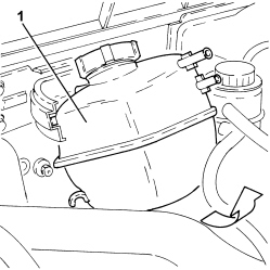
1. Loosen the bands and disconnect the engine coolant supply reservoir pipes.
1. Rotate the engine coolant supply reservoir as illustrated in the diagram, then remove it.
1. Disconnect the rapid connectors for the air conditioning system heater coolant inlet and outlet pipes.
1. Disconnect the gear selector cable.2. Disconnect the gear engagement cable.
1. Open the clips (1a) and release the gear selector and engagement cables (1b) from the mounting bracket.
1. Release the retaining clip (1a) and disconnect the pipe (1b) between the damper and the clutch operating cylinder (1b), operating cylinder side. | Collect the bake/clutch fluid that comes out in a suitable container. |
2. Disconnect the electrical connection from the reversing light switch.3. Undo the bolt (3a) and disconnect the earth lead (3b) from the gearbox.
1. Unscrew bolts (1a), loosen collar (1b) and remove the sleeve (1c) and rigid air intake pipe (1d) to the throttle body.2. Disconnect the rapid connector for the vacuum intake pipe from the vacuum pump.3. Loosen the band and disconnect the upper coolant inlet hose to the radiator, thermostat side.
1. Disconnect the electrical connection from the turbocharger vane position actuator solenoid valve.2. Unscrew nuts (2a) and move aside the turbocharger vane position actuator control solenoid valve (3b).
- Disconnect the electrical connection from the water presence sensor on the fuel filter.- Disconnect the electrical connection from the particulate filter differential pressure sensor.1. Unscrew the nut and move the glow plug control unit as necessary.2. Disconnect the electrical connections from the heater plugs control unit.3. Remove the control unit for glow plugs.4. Disconnect the intermediate engine wiring coupling.
1. Disconnect the electrical connections from the power steering pump.
1. Disconnect the electrical connection from the air conditioning system multi-stage pressure switch. | Description | Connector |
|---|
| 1 | 4 stage pressure switch | See K010 4 STAGE PRESSURE SWITCH |
2. Undo the nut (2a) and disconnect the earth lead (2b).
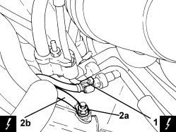
- Secure the engine cooling radiator to the headlamp beam.1. Undo the nut (1a) and disconnect the steering links (1b) from the steering knuckles using the tool (1c).| Tool | Description | Function | Validity |
|---|
| 1871000700 | Extractor | Extracting steering rod from steering knuckle | |
2. Undo the nuts (2a) and disconnect the rear suspension anti-roll bar joints (2b), anti-roll bar side.
1. Undo the fixing bolt (1a) and disconnect the steering column (1b) from the steering box. | The bolt is the pre-treated type and it therefore cannot be reused when refitting. |
1. Remove right front hub cap (1a) using the tool (1b).| Tool | Description | Function | Validity |
|---|
| 1870470560 | Extractor | Removing wheel hub cap | |
1. Undo the nut (1a) securing the right front driveshaft to the wheel hub using tool (1b) for counter-torque.| Tool | Description | Function | Validity |
|---|
| 1870815000 | Counter-torque | Loosen/tighten timing driven toothed pulley fixing boltLoosen/tighten nut securing front driveshaft to wheel hub | 1.9 JTD 16V1.9 JTD 8V |
1. Undo the lower bolt securing the left front shock absorber to the knuckle.
1. Undo the bolt (1a) and disconnect the left lower track control arm for the front suspension (1b) from the steering knuckle pulling it downwards. | Do not use expansion tools for disconnecting the track control arm from the steering knuckle. |
1. Disconnect the left driveshaft from the differential using a suitable lever and move it to the side.
1. Undo the lower bolt securing the right front shock absorber to the knuckle.
1. Undo the nuts (1a) and disconnect the rear front suspension anti-roll bar link (1b) from the anti-roll bar.
1. Undo the bolt (1a) and disconnect the right lower track control arm for the front suspension (1b) from the steering knuckle pulling it downwards. | Do not use expansion tools for disconnecting the track control arm from the steering knuckle. |
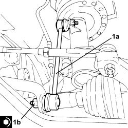
1. Use the tool to move the right driveshaft back from the wheel hub.| Tool | Description | Function | Validity |
|---|
| 2000001600 | Extractor | Retract driveshaft from front wheel hub | |
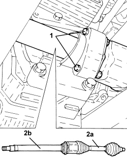
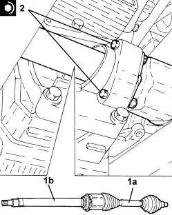
1. Loosen the bolts fixing the intermediate driveshaft to the mounting.2. Remove the right drive shaft (2a) with intermediate drive shaft (2b).
Op. 1076B72 INTERMEDIATE EXHAUST PIPE WITH HOSE SECTION - R+R1. Undo the nuts (1a) and remove the engine coolant radiator mounts (1b).
- Position a hydraulic jack beneath the power unit.1. Unscrew the left engine mount flexible block bolt, front suspension frame side.
1. Undo the bolt securing the lower gearbox reaction rod to the bracket on the gearbox.
1. Position a hydraulic lift (1a) using tools (1b) and (1c) to support the front suspension frame. | Fit the guide pins (arrowed) into the front suspension frame body. |
| During disassembly, lower the two locating pins (1d) on the body. |
| Tool | Description | Function | Validity |
|---|
| 1870835001 | Hydraulic lift | Supporting front suspension frameRear suspension crossmember support | |
| Tool | Description | Function | Validity |
|---|
| 2000001700 | Chassis | Removing-refitting front suspension frame | |
| Tool | Description | Function | Validity |
|---|
| 2000001800 | Support | Removing-refitting front suspension frame | |
- If the above hydraulic lift is not available, use a general hydraulic lift plus the adaptor shown in the drawing, which must be made up by the workshop to allow the use of the above frames
(*): Ensure the shank diameter fits the hydraulic lift used.
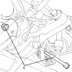
1. Unscrew bolts (1a) and (1b) and remove the brackets securing the frame to the body (1c).
1. Undo the bolts fixing the front suspension frame to the bodyshell.
1. Lower the hydraulic jack and remove the front suspension frame assembly.
- Postion a suitable footboard beneath the power unit.1. Support the power unit using a hydraulic hoist (1a) and the tool (1b) connected to the mounting brackets (1c).| Tool | Description | Function | Validity |
|---|
| 1871001700 | Balance | Removing-refitting power unit | |
1. Undo the bolts fixing the gearbox side power unit flexible mounting to the rigid support.
1. Undo the bolts fixing the timing side power unit support flexible mounting, rigid support side.
- Slowly lower the power unit with the hydraulic hoist until it rests on the board positioned previously.- Release the power unit from the support tools.
Refitting
(
Removing
)
- Secure the power unit using the support tools.- Place the power unit in its housing using the hydraulic hoist.1. Tighten the bolts fixing the timing side power unit support flexible mounting, rigid support side to the recommended torque.| Component | Fastening | dia | Value (daNm) | Validity |
|---|
| Timing side power unit rigid support flexible mounting | Bolt | M10 | (rigid support side) 5.0 - 6.0 | 1.82.21.9 JTD 16v1.9 JTD 8v |
1. Tighten the bolts fixing the gearbox side power unit flexible mounting to the rigid support to the recommended torque.| Component | Fastening | dia | Value (daNm) | Validity |
|---|
| Gearbox side support flexible mounting | Bolt | M10 | (support side) 5.0 - 6.0 | |
- Remove the hydraulic hoist and tool used for supporting the power unit safely.| Tool | Description | Function | Validity |
|---|
| 1871001700 | Balance | Removing-refitting power unit | |
- Remove the support used for supporting the power unit.1. Refit the front suspension frame assembly using the mounting tools and hydraulic jack. | During refitting, remove both locating pins (1a), which must fit into the holes in the underbody during assembly. |
1. Tighten the bolts fixing the front suspension crossmember to the bodyshell to the recommended torque.| Component | Fastening | dia | Value (daNm) | Validity |
|---|
| Front suspension frame | Front-rear bolts (to replace) | M12 | (bodyshell side) 9.0 - 11.0 + 90° | |
1. Place the underbody reinforcement (1a) in its housing and secure it tightening the new bolts (1b), (1c) and (1d) to the recommended torque.| Component | Fastening | dia | Value (daNm) | Validity |
|---|
| Underbody reinforcements | Inner bolt (to replace) | M12 | (bodyshell side) 8.1 - 9.9 + 45° | |
| Component | Fastening | dia | Value (daNm) | Validity |
|---|
| Underbody reinforcements | Outer bolt (to replace) | M10 | (bodyshell side) 5.0 - 6.1 + 45° | |
| Component | Fastening | dia | Value (daNm) | Validity |
|---|
| Underbody reinforcements | Bolt (to be replaced) | M12 | (front suspension frame side) 9.0 - 11.0 + 90° | |
- Remove the tools and the hydraulic jack used to support the front suspension frame.| Tool | Description | Function | Validity |
|---|
| 1870835001 | Hydraulic lift | Supporting front suspension frameRear suspension crossmember support | |
| Tool | Description | Function | Validity |
|---|
| 2000001700 | Chassis | Removing-refitting front suspension frame | |
| Tool | Description | Function | Validity |
|---|
| 2000001800 | Support | Removing-refitting front suspension frame | |
1. Undo the bolt securing the lower gearbox reaction rod to the mounting bracket on the gearbox to the specified torque.| Component | Fastening | dia | Value (daNm) | Validity |
|---|
| Lower reaction rod for gearbox | Bolt | M12 | (bracket side on gearbox) 7.5 - 8.5 | |
1. Tighten the left engine mount flexible block bolt, front suspension frame side, to the specified torque.| Component | Fastening | dia | Value (daNm) | Validity |
|---|
| Flexible mounting for left side engine support | Bolt | M12 | (front suspension frame side) 7.5 ÷ 8.5 | |
- Remove the hydraulic jack from beneath the power unit1. Position the engine cooling radiator mount (1a) in its housing and secure it tightening the bolts (1b) to the recommended torque.| Component | Fastening | dia | Value (daNm) | Validity |
|---|
| Engine cooling radiator supports | Bolt | - | (front suspension frame side) 1.5 | |
Op. 1076B72 INTERMEDIATE EXHAUST PIPE WITH HOSE SECTION - R+R1. Refit the right drive shaft (1a) complete with intermediate drive shaft (1b).2. Tighten the bolts fixing the intermdiate driveshaft to the mounting to the recommended torque.| Component | Fastening | dia | Value (daNm) | Validity |
|---|
| Intermediate driveshaft | Bolt | M8 | (support side) 2.3 - 2.8 | 2.2 |
1. Connect the front suspension lower track control arm (1a) to the steering knuckle and secure it tightening a new bolt (1b) to the recommended torque.| Component | Fastening | dia | Value (daNm) | Validity |
|---|
| Front suspension lower track control arm | Bolt (to be replaced) | M10 | (steering knuckle side) 2.7 - 3.3 + 60° | |
1. Connect the right front antiroll bar link (1a), antiroll bar side, and tighten nut (1b) to the specified torque.| Component | Fastening | dia | Value (daNm) | Validity |
|---|
| Front suspension anti-roll bar joint | Nut | M12 | (anti-roll bar side) 6.0 - 7.0 | |
1. Tighten the new lower bolt fixing the right front shock absorber to the steering knuckle to the recommended torque.| Component | Fastening | dia | Value (daNm) | Validity |
|---|
| Front shock absorber | Bolt (to be replaced) | M12 | (steering knuckle side) 7.7 - 9.4 +75° | |
- Connect the left driveshaft to the differential.1. Connect the left lower suspension lower track control arm (1a) to the steering knuckle and secure it tightening a new bolt (1b) to the recommended torque.| Component | Fastening | dia | Value (daNm) | Validity |
|---|
| Front suspension lower track control arm | Bolt (to be replaced) | M10 | (steering knuckle side) 2.7 - 3.3 + 60° | |
1. Tighten the new lower bolt fixing the right front shock absorber to the steering knuckle to the recommended torque.| Component | Fastening | dia | Value (daNm) | Validity |
|---|
| Front shock absorber | Bolt (to be replaced) | M12 | (steering knuckle side) 7.7 - 9.4 +75° | |
1. Tighten nut (1a) securing the right front drive shaft to the wheel hub using tool (1b) for countertorque.| Component | Fastening | dia | Value (daNm) | Validity |
|---|
| Front wheel hub | Nut (to replace) | M24 | (driveshaft side) see operation 4450C28 | |
- Refit a new front hub cap in its seat using the appropriate tool.1. Connect the steering column (1a) to the power steering box pinion and secure by tightening a new bolt (1b) to the specified torque.| Component | Fastening | dia | Value (daNm) | Validity |
|---|
| Steering column | Bolt (to be replaced) | M8 | (power assisted steering box side) 2.3 - 2.8 | |
1. Connect the left front antiroll bar link (1a) to the antiroll bar and tighten nut (1b) to the specified torque.| Component | Fastening | dia | Value (daNm) | Validity |
|---|
| Front suspension anti-roll bar joint | Nut | M12 | (anti-roll bar side) 6.0 - 7.0 | |
2. Connect the left steering link (2a) to the front steering knuckles and tighten the nut (2b) to the specified torque.| Component | Fastening | dia | Value (daNm) | Validity |
|---|
| Steering rods | Nut | M12 | (steering knuckle side) 3.0 - 4.0 | |
- Release the engine cooling radiator from the headlamp beam.- Connect the earth lead and tighten the nut.- Connect the electrical connection to the air conditioning system multi-stage pressure switch.- Connect the electrical connections to the power steering pump.- Connect the intermediate engine wiring coupling.- Connect the electrical connections to the heater plugs control unit.- Place the heater plugs control unit in position and secure it using the nut.- Connect the electrical connection to the particle filter differential pressure sensor.- Connect the electrical connection to the water presence sensor on the fuel filter.- Refit the turbocharger vane position actuator control solenoid valve and secure with nuts.- Connect the electrical connection to the turbocharger vane position actuator solenoid valve.- Connect the radiator upper coolant inlet hose, thermostat side, and tighten the band.- Connect the vacuum pipe rapid connector to the vacuum pump.- Place the throttle body rigid air inlet pipe in its housing complete with hose and tighten the bolts and the band.- Connect the earth lead to the gearbox and secure it using the bolt.- Connect the electrical connection to the reversing light switch.- Connect the pipe between the damper and clutch operating cylinder, operating cylinder side and secure it using the retaining clip.- Fasten the gear selection and engagement cables to the mounting bracket securing them using the clips.- Connect the gear selector and engagement cables.- Connect the rapid connectors for the air conditioning system heater coolant inlet and outlet pipes.- Place the engine coolant supply reservoir in its housing.- Connect the pipes to the engine coolant supply reservoir and tighten the bands.- Connect the fuel supply pipe rapid connector, pressure pump side.- Connect the rapid connector for the fuel return pipe, fuel return manifold side.- Place the air outllet hose from the turbocharger back in its housing and secure it using the bands.- Connect the lower coolant inlet hose from the radiator, water pump rigid coolant inlet pipe side and tighten the band.- Refit the air filter with air flow meter and corrugated hose in its seat.- Connect the cold air intake pipe to the air filter.- Connect the corrugated hose to the turbocharger air inlet pipe and tighten the band.- Connect the electrical connection to the air flow meter.- Connect the electrical connections to the diesel electronic injection system control unit.1. Connect the coolant inlet and outlet pipe flange (1a) to the air conditioner compressor and secure by tightening bolt (1b) to the specified torque.
 | Replace any O-Rings for the connectors using green coloured seals only which are resistant to the R134a refrigerant fluid.Lubricate the connector threads using anti-freeze. |
| Component | Fastening | dia | Value (daNm) | Validity |
|---|
| EVAPORATOR/COMPRESSOR PIPE ON COMPRESSOR | Bolt | M8 | 1,8 ÷ 2,2 | |
- Place the intercooler air intake sleeve back in its housing and secure it using the bands.- Tighten the coolant drain plug to the radiator. Op. 7055B90 LEFT FRONT WHEEL ARCH LINER - R.R. Op. 7055B91 RIGHT FRONT WHEEL ARCH LINER - R.R. Op. 7055B66 ENGINE COMPARTMENT DUST COVER IN RIGHT FRONT WHEEL ARCH - R.R. Op. 4450B12 FRONT WHEELS (TWO) - R+R Op. 0010T84 COOLANT FOR AIR CONDITIONING SYSTEM - DEHYDRATE AND REPRESSURIZE Op. 5530B52 BATTERY SUPPORT/DRIP TRAY - R.R Op. 5530B10 BATTERY - R+R Op. 0010T20 ENGINE COOLANT - CHANGE Op. 0010T64 BRAKE AND/OR CLUTCH FLUID CHECK LEVEL AND TOP UP AS NECESSARY Op. 0010T67 HYDRAULIC CLUTCH SYSTEM - BLEED AIR Op. 7055B54 UNDER ENGINE PROTECTION/GUARD - R.R. Op. 1016A10 SOUND-PROOFING COVER - R.R- Remove the vehicle from the lift.