199002367 - 1072B50 AIR CHAMBER - R.R.
| Description | Connector | |
|---|---|---|
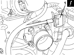
| 1 | Integrated throttle body actuator | See N075 BUILT-IN THROTTLE BODY ACTUATOR |
| Description | Connector | |
|---|---|---|
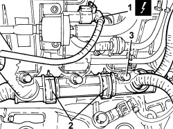
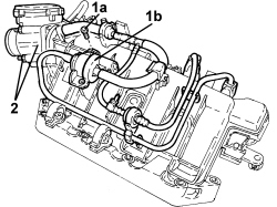
| 1 | Fuel vapour recovery solenoid valve | See L010 FUEL VAPOUR RECOVERY SOLENOID VALVE |
| Description | Connector | |
|---|---|---|
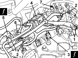
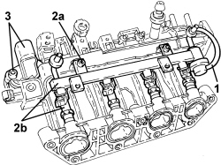
| 3 | Injector | See N070 INJECTOR |
| Description | Connector | |
|---|---|---|
| 6 | Air pressure - temperature sensor | See K044 AIR PRESSURE - TEMPERATURE SENSOR |
| Component | Fastening | dia | Value (daNm) | Validity |
|---|---|---|---|---|
| Air chamber | Bolt (to be replaced) | M7 | 1.3 ÷ 1.7 | 1.4 16v TJet |
| Component | Fastening | dia | Value (daNm) | Validity |
|---|---|---|---|---|
| Air chamber | Bolt (to be replaced) | M7 | 1.3 ÷ 1.7 | 1.4 16v TJet |