323001423 - 1016C10 SINGLE CYLINDER HEAD - R.R. AND REPLACE GASKET

Removing ( Refitting ) - Position the vehicle on a lift.    Op. 5530B10 BATTERY - R+R     Op. 5530B52 BATTERY SUPPORT/DRIP TRAY - R.R     Op. 1048A10 AIR FILTER ASSEMBLY - R.R.     Op. 1048A23 COLD AIR INTAKE FOR AIR FILTER - R.R     Op. 4450B04 RIGHT FRONT WHEEL - R.R     Op. 7055B66 ENGINE COMPARTMENT DUST COVER IN RIGHT FRONT WHEEL ARCH - R.R.     Op. 1060G90 SYSTEM CABLE LOOM - R.R.     Op. 1084B40 ENGINE OIL DELIVERY PIPE TO TURBOCHARGER - R + R     Op. 1072C44 EXHAUST MANIFOLD HEAT SHIELD - R.R.    Op. 1084B42 ENGINE OIL RETURN PIPE FROM TURBO - R + R     Op. 1064A11 TURBOCHARGER WITH CATALYTIC CONVERTER - R.R.     Op. 1008A46 POWER UNIT RIGID SUPPORT - TIMING SIDE - R.R.     Op. 1016B10 SINGLE CAMSHAFT HOUSING - REPLACE GASKET     Op. 0010T20 ENGINE COOLANT - CHANGE 1. Loosen the band and disconnect the upper radiator coolant inlet hose, thermostat side.2. Loosen the band and disconnect the oil vapour recircuation hose from the rigid pipe.3. Loosen the band and remove the air intake pipe to the turbocharger.4. Loosen the collar securing the coolant supply pipe to the engine oil heat exchanger, thermostat side.5. Loosen the band and disconnect the coolant outlet pipe from the climate control system heater, water pump rigid inlet pipe side.
1. Undo the bolts and disconnect the pipe from the heat exchanger to the air capacity chamber, chamber side.2. Loosen the band and disconnect the coolant supply pipe to the climate control system heater, on the EGR system exhaust gas/water heat exchanger side.
1. Undo the retaining bolt (1a) and remove the engine oil dipstick tube (1b).2. Loosen the band and disconnect the condensed engine oil recovery pipe (2a) from the separator (2b).
- Loosen the band and disconnect the condensed engine oil recovery pipe, oil vapour separator side.1. Unscrew the bolt securing the water/exhaust gas heat exchanger for the EGR to the crankcase.
1. Working through the hole in the camshaft cover, unscrew the bolt securing the pad fastening the timing chain to the cylinder head.2. Undo the bolts fixing the timing cover to the cylinder head.
1. Undo bolts (1a) and remove cylinder head assembly (1b).2. Remove the cylinder head gasket.
Refitting ( Removing ) 1. Measure the piston projection in two places at 180° on the gudgeon pin axis using the gauge and support and take the average of the two values measured for each piston.
ToolDescriptionFunctionValidity
1870404001Dial gauge mountPiston projection from cylinder head support plane check1.3 Multijet
- Select the correct size cylinder head gasket, according to the maximum value of the averages for the protrusion for each individual piston.
MeasurementValueValidity
Cylinder head gasket size with average maximum piston projection (mm)projection0.028 ÷ 0.127thickness (no opening)0.67 ÷ 0.771.3 Multijet
MeasurementValueValidity
Cylinder head gasket size with average maximum piston projection (mm)projection0.128 ÷ 0.227thickness(one opening)0.77 ÷ 0.871.3 Multijet
MeasurementValueValidity
Cylinder head gasket size with average maximum piston projection (mm)projection0.228 ÷ 0.327thickness (two openings)0.87 ÷ 0.971.3 Multijet
1. Apply silicon sealant in the contact area between the crankcase and timing cover.2. Position the cylinder head locating bushes on the crankcase as shown in the figure.
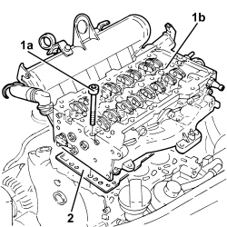
The locating bushes between the crankcase and cylinder head are shorter (10.0 mm) than the bushes between the cylinder head and the cylinder head extension. Take gret care not to reverse them as this could impair engine operation.
3. Position the cylinder head gasket in the thickness selected previously and fit onto the locating bushes.4. Apply silicon sealant to the cylinder head gasket in the contact area with the timing cover.5. Also apply a strip of the same sealant to the surface of the timing cover gasket following the black line of silicon on the actual gasket.
Apply a layer of sealant to the timing cover gasket so that it is not too thick and avoid excess sealant inside the timing cover.
- Position the cylinder head on the engine block, fitting into the locating bushes.
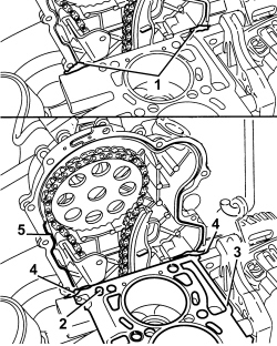
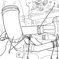
Before moving the cylinder head, apply grease to the belt tensioner piston to prevent it emerging accidentally during moving.
1. Screw in and tighten the bolts fixing the timing cover to the cylinder head to torque.
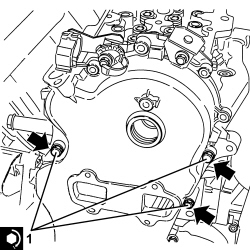
During this stage, do not tighten the bolt into hole (a).
ComponentFasteningdia  Value (daNm)Validity
Crankshaft oil seal front coverBoltM60.8 ÷ 1.0
- Position the cylinder head bolts in their seats and screw in partly without tightening.1. Tighten only the two bolts shown in the figure securing the cylinder head to the engine block to the specified torque of 2.5 daNm.2. Loosen the bolts fixing the timing cover tightened previously.3. Continue tightening the bolts fixing the camshaft housing to a torque of 2.5 daNm following the order illustrated working gradually towards the timing cover.
1. Tighten the cylinder head bolts (1a) to the recommended torque using the angular tightening tool (1b).
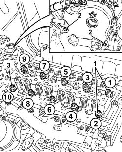
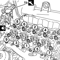
Follow the order shown in the diagram for each tightening sequence.The nominal tightening of 4.0 daNm is performed in two stages: a pretightening to 2.0 daNm followed by an additional tightening of 2.0 daNm.
ComponentFasteningdia  Value (daNm)Validity
Cylinder headBoltM103.8 ÷ 4.2 + 90° + 90°1.3 Multijet
ToolDescriptionFunctionValidity
1860942000Torque wrenchTighten bolts to torque plus angle
1. Insert the third bolt securing the timing cover to the cylinder head, then tighten the three bolts securing the timing cover to the cylinder head to the specified torque.
ComponentFasteningdia  Value (daNm)Validity
Crankshaft oil seal front coverBoltM60.8 ÷ 1.0
- Tighten the bolt securing the timing belt fixed pad to the cylinder head.- Tighten the bolt securing the water/exhaust gas heat exchanger for the EGR to the engine block.- Connect the condensed engine oil recovery pipe, oil vapour separator side, and tighten the band.- Place the engine oil dipstick pipe back in its housing and fasten it with the bolt.- Connect the climate control system heater coolant supply pipe, on the EGR system exhaust gas/water heat exchanger side and tighten the band.- Connect the pipe from the heat exchanger to the air capacity chamber, chamber side, and tighten the band.- Connect the upper coolant input sleeve to the radiator, thermostat side, and tighten the band.    Op. 1016B10 SINGLE CAMSHAFT HOUSING - REPLACE GASKET     Op. 1008A46 POWER UNIT RIGID SUPPORT - TIMING SIDE - R.R.     Op. 1064A11 TURBOCHARGER WITH CATALYTIC CONVERTER - R.R.     Op. 1084B42 ENGINE OIL RETURN PIPE FROM TURBO - R + R     Op. 1072C44 EXHAUST MANIFOLD HEAT SHIELD - R.R.    Op. 1084B40 ENGINE OIL DELIVERY PIPE TO TURBOCHARGER - R + R     Op. 1060G90 SYSTEM CABLE LOOM - R.R.     Op. 7055B66 ENGINE COMPARTMENT DUST COVER IN RIGHT FRONT WHEEL ARCH - R.R.     Op. 4450B04 RIGHT FRONT WHEEL - R.R     Op. 1048A23 COLD AIR INTAKE FOR AIR FILTER - R.R     Op. 1048A10 AIR FILTER ASSEMBLY - R.R.     Op. 5530B52 BATTERY SUPPORT/DRIP TRAY - R.R     Op. 5530B10 BATTERY - R+R     Op. 0010T20 ENGINE COOLANT - CHANGE - Remove the vehicle from the lift.