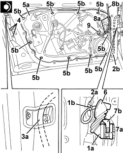
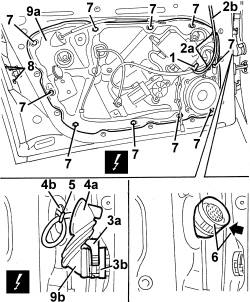
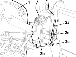
939011109 - 7005A08 INTERIOR SUPPORT FRAME FOR ONE SIDE DOOR - R.R. WITH DOOR PANEL REMOVED
| Description | Component |
|---|---|
| DRIVER''S DOOR JUNCTION UNIT | See M066 DRIVER'S DOOR CONTROL UNIT (NPG) |
| PASSENGER SIDE DOOR JUNCTION UNIT | See M067 PASSENGER DOOR CONTROL UNIT (NPP) |
| Description | Component |
|---|---|
| REAR JOINT/FRONT DOOR DRIVER SIDE | See D030 DRIVER'S FRONT DOOR COUPLING |
| REAR JOINT/FRONT DOOR PASSENGER SIDE | See D031 PASSENGER FRONT DOOR COUPLING |
| Component | Fastening | dia | Value (daNm) | Validity |
|---|---|---|---|---|
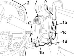
| DOOR LOCK | Bolt | M6x12 | 0.7 ÷ 1.1 |
| Component | Fastening | dia | Value (daNm) | Validity |
|---|---|---|---|---|
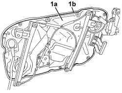
| DOOR INNER FRAME | Bolt | M6x16 | 0.7 ÷ 1.1 |