2398713 - 5580C air bag system
INTRODUCTION
The car is fitted with an electronically-controlled
system which, in the case of a front-end or side crash of medium-high severity
activates the safety devices.The front protection system includes dual
(driver and passenger) , dual stage, front Air Bags, front seat
belts with pretensioners and load limiters, with a decentralised
supplementary sensor for detecting impacts and a manual passenger
Air Bag disabling switch.The side protection system comprises two
Window Bags, housed in the side members under the roof and two Side
Bags in the front seats are available as optional extras.The front protection system uses the new
activation logic known as the Smart 2 Air Bag which is capable of
automatically adapting the activation parameters depending ont he
seriousness of the impact.The driver and passenger front Air Bags
are the dual activation stage type: when the impact is of medium
severity, the electrnic control unit only operates the first activation
stage for the Air Bags avoiding the intake of energy not needed
for the protection of the occupant.Conversely, for very serious impacts, the
control unit activates both stages in order to be able to absorb
the increased kinetic energy of the occupant before the impact against
the steering wheel or the dashboard.In addition, an additional ECS Early Crash
Sensor located near the bonnet lock; assists the electronic control
unit in anticipating the intervention of the Air Bags compared with
a conventional system so that the activation stage is completed
even before the occupant starts to move forwards towards the steering
wheel or the dashboard. In addition, this sensor detects underbody
impacts or stresses for which the activation of the Air Bags is
not necessary because there is no risk to the occupants. | The components of the Air Bag
system have been designed to work on a specific car. They therefore
may NOT be tampered with, adapted or installed on other types of
vehicles. |
| The vehicle should be handed over
to the customer with the passenger Air Bag deactivtion switch in
the ON position and the warning light in the instrument panel off. |
| For safety reasons continuity
checks on the wiring are NOT permitted. |
The Air Bag system components are connected
electrically by dedicated wiring, integrated in the dashboard wiring
loom for the front devices, and in the rear wiring loom for the
side devices and the pretensioners.The control unit is connected to the system
by means of two connectors, one for the front cable and one for
the rear cable.The control unit is connected to the vehicle
CAN through which it exchanges information with the other nodes,
lights up the warning lights in the instrument panel and carries
out the diagnostic operations.As the control unit is a CAN node,
the Air Bag system has the following opportunities:
- connection to the diganostic socket via the CAN and
no longer with the dedicated K line;
- connection to the instrument panel for operating the
warning lights;
- connection to the panel to satisfy the EuroNCAP protocol
which involves a series of warnings if the seat belts are not fastened.
- connection to the Body Computer for the possible end
of line customization (Proxi) and consequent reduction in the number
of Spares.
The passenger's front Air Bag module can
be deactivated voluntarily, by a specific key switch located beside
the dashboard. | GRAVE DANGER! If a child seat
is fitted on the front passenger seat, the front Air Bag module
MUST be deactivated. |
| If the vehicle is equipped with
Side Bags, the deactivation of the passenger front Air Bag module
does not disable the side modules. Thus in the event of a side impact,
protection is also offered to any child who may be on board. |
COMPOSITION
The system comprises the following
devices:
- an electronic control unit;
- dual driver and passenger front Air Bags with dual stage
activation
- an additional decentralized ECS impact detection sensor
(Early Crash Sensor)
- a manual passenger Air Bag disabling switch,
- two Side Bags on the front seats,
- two Window Bag modules for protecting the sides of the
occupants;
- two side impact sensors fitted in the side pillars;
- two electronic pretensioners on the front seat belts;
To indicate the state of efficiency,
the system has:
- fault warning light (red) on the instrument panel;
- passenger Air Bag disabled warning light in the instrument
panel;
- connection via the B-CAN with the diagnostic socket
- incorporated in the Body Computer - for checking the operation using
the EXAMINER.
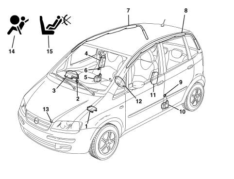
1 - Electronic control unit
2 - Passenger Air Bag disabling switch
3 - Passenger's Air Bag module
4 - Passenger's Side Bag module
5 - Passenger seat belt pretensioner
6 - Passenger side impact sensor
7 - Passenger's Window Bag module
8 - Driver's Window Bag module
9 - Driver's side impact sensor
10 - Driver's pretensioner
11 - Driver's Side Bag module
12 - Driver's Air Bag module
13 - Front impact sensor
14 - Air Bag system failure warning light
15 - Passenger front Air Bag disabling warning light
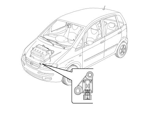
ELECTRONIC CONTROL UNIT
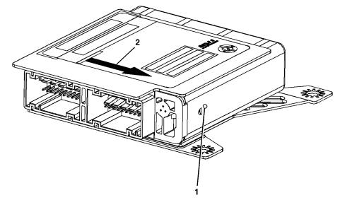
The following figure shows the
control unit.1 Electronic control unit
2 Direction of travel indication
ELECTRONIC CONTROL UNIT
The control unit represents the
central processing unit of the occupant protection system and is
fastened securely to the vehicle floor pan near the centre tunnel.
It manages all the system detection and activation devices, processing
the signals which come from the various sensors around the vehicle
and from those fitted inside. | The control unit must always be
fitted with the arrow 2 stamped on the adhesive plate facing the
vehicle's direction of travel. Always check that there are no foreign
bodies between the control unit and the bodyshell, tightening the bolts
to the recommended torque. |
COMPOSITION
The control unit contains an
electronic deceleration sensor which gives the go ahead for the
activation of the safety devices. This sensor comprises two direction
accelerometers which include the front ECS and power the operation
of the side sensors. | If the control unit is dropped
or is subjected to unusual impact during handling, the control unit
MUST be replaced. |
OPERATION
Frontal crashWhen the severity of the impact is medium,
the electronic control unit only commands the first activation stage
for the Air Bags preventing the intake of energy not needed for
the protection of the occupant.Conversely, for very serious impacts, the
control unit activates both stages in order to be able to absorb
the increased kinetic energy of the occupant before the impact against
the steering wheel or the dashboard.In addition, the E.C.S. assists the electronic
control unit to anticipate the intervention of the Air Bags compared
with a conventional system so that the activation of the Air Bags
is completed before the occupant even starts moving forwards towards
the steering wheel or the dashboard.Side impactSimilarly, when there is a side impact,
the control unit is capable of recognizing the direction and the
intensity, activating the two Air Bags fitted on the side affected
by the impact. In order to provide complete cover for side impacts,
there are two satellite sensors located in the centre pillars.When a side impact occurs, the satellite
sensors detect the direct crash signal along the car's transversal
axis, and send it to the control unit. This signal, processed by
a microprocessor inside the control unit, detects the severity
of the side impact and decides whether to set off the side Air Bag
on the side concerned only if the safety sensor is enabled by the
control unit.The Side Bags (and head bags if fitted)
are activated simultaneously and independently of the front safety
devices.After each activation of one of the systems
operated (pretensioners, front Air Bags, side Air Bags), the control
unit memorises the activation in non-deletable memory and causes
the fault warning light on the instrument panel to come on.Before being replaced, the control
unit guarantees the activation of the individual devices within
the following limits:
- 3 impacts with activation of the front seat belt pretensioners
only;
- 3 impacts in total (left and right) with the activation
of the side Air Bags;
- 1 impact with activation of the pretensioners and front
Air Bags;
- any combination of the above cases until one of the
limits indicated is reached.
If one of the limits described has not been
reached, it will be possible, after restoring the operating conditions
of the system, to reuse the control unit after carrying out the
RESET procedure by means of the EXAMINER. The last activation, corresponding
to the maximum number, will prevent further reset conditions.
CONTROL UNIT PIN OUT
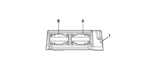
The diagram below shows the control
unit and Pin Out1 - Electronic control unit
A - FRONT CONNECTOR (black coloured dashboard wiring)
B - REAR CONNECTOR (light blue coloured rear wiring)
CONTROL UNIT PIN OUT
FRONT CONNECTOR| PIN | OPERATION |
|---|
| 1 | EARTH |
| 2 | CONTROL UNIT SUPPLY CONTROLLED BY IGNITION |
| 3 | N.C. |
| 4 | N.C. |
| 5 | N.C. |
| 6 | N.C. |
| 7 | B.CAN-A LINE |
| 8 | B.CAN-A LINE |
| 9 | PASSENGER BAG DEACTIVATOR |
| 10 | N.C. |
| 11. | N.C. |
| 12. | FRONT IMPACT SENSOR ECS |
| 13 | PASSENGER AIR BAG 1ST STAGE (+) |
| 14 | PASSENGER AIR BAG 1ST STAGE (-) |
| 15 | DRIVER'S AIR BAG 1ST STAGE (-) |
| 16 | DRIVER'S AIR BAG 1ST STAGE (+) |
| 17 | DRIVER'S AIR BAG 2ND STAGE (+) |
| 18 | DRIVER'S AIR BAG 2ND STAGE (-) |
| 19 | PASSENGER AIR BAG 2ND STAGE (-) |
| 20 | PASSENGER AIR BAG 2ND STAGE (+) |
| 21 | N.C. |
| 22 | N.C. |
| 23 | N.C. |
| 24 | N.C. |
REAR CONNECTOR| PIN | OPERATION |
|---|
| 1 | PASSENGER SIDE IMPACT SENSOR |
| 2 | DRIVER SIDE IMPACT SENSOR |
| 3 | N.C, |
| 4 | N.C, |
| 5 | N.C, |
| 6 | N.C, |
| 7 | N.C, |
| 8 | N.C, |
| 9 | N.C, |
| 10 | DRIVER'S SEAT BELT NOT FASTENED SWITCH |
| 11. | N.C, |
| 12. | N.C, |
| 13 | PASSENGER WINDOW BAG (+) |
| 14 | PASSENGER WINDOW BAG (-) |
| 15 | DRIVER'S WINDOW BAG (-) |
| 16 | DRIVER'S WINDOW BAG (+) |
| 17 | PASSENGER SIDE BAG (+) |
| 18 | PASSENGER SIDE BAG (-) |
| 19 | DRIVER'S SIDE BAG (-) |
| 20 | DRIVER'S SIDE BAG (+) |
| 21 | FRONT PRETENSIONER PASSENGER (+) |
| 22 | FRONT PRETENSIONER PASSENGER (.) |
| 23 | FRONT PRETENSIONER DRIVER (-) |
| 24 | FRONT PRETENSIONER DRIVER (+) |
SELF-DIAGNOSIS
The control unit carries out a continuous
autodiagnosis of the system operation. In particular:
- it detects and memorizes any faults
- diagnoses the connections with the system components
and the possible type of fault;
- it signals the onset of these faults via the special
warning light in the instrument panel.
The faults memorised in the control unit
may only be deleted after the fault has been repaired using the
EXAMINER diagnostic equipment. | If a fault is detected in the
passenger Air Bag disabling switch, for safety reasons this is considered
by the control unit to be in the OFF position, so the operation
of the module is inhibited and the warning light on the instrument panel
comes on. |
DRIVER'S AIR BAG MODULE
The figure below shows a view
of assembly.1 - Cover
2 - Bag
3 - Casing
4 - Gas generator connectors
SPECIFCATIONS
The Air Bag is a passive safety
device made up of a bag which, in the case of a frontal impact,
inflates placing itself between the body of the driver and the structure
of the front part of the passenger compartment. The Air Bag module
is installed in the centre of the steering wheel, and its cover
also acts as the horn control.
COMPOSITION
The module consists of:
- a plastic cover; which in the case of activation tears
in predefined points to allow the bag to expand correctly;
- a bag, with a volume of about 60 litres, made of nylon
fabric to minimise skin abrasions in the case of contact, and folded in
a particular way so that it inflates gradually and not directly
facing the driver;
- two pyrotechnic gas generators;
- a casing.
OPERATION
The Bag is inflated by a gas
generator which has two intervention stages which can be activated
separately depending on the severity of the impact.Each gas generator is activated by means
of two electrical resistances which burn the propellant inside the
generator allowing the bag to expand.When fully inflated, the cushion is in the
optimum position to carry out its function to retain the occupant.
The Bag deflates immediately, thanks to an opening in the lower
part of the bag. This opening also performs the function of 'softening'
the contact between the passenger and the bag preventing the risk
of abrasions
PASSENGER AIR BAG MODULE
The figure below shows a view
of assembly:1 - Cover
2 - Bag
3 - Gas generator connectors
SPECIFCATIONS
The passenger Air Bag module
is a passive safety device which, in the case of a frontal impact,
protects the front passenger, by means of a bag which places itself
between the occupant and the dashboard.
COMPOSITION
The module consists of:a metal restraining support;a bag card cover which, in the case of activation,
opens along a pre-cut fracture line, allowing the bag to escape;a bag, with a volume of about 105 litres,
made of nylon fabric in order to minimise skin abrasions in the
event of contact, and folded in a particular way so that it does
not inflate directly towards the occupant;- two pyrotechnic gas generators;- fitting brackets on the crossmember;
OPERATION
The activation logic for the
passenger Bag is identical to that of the driver's side.The inflation of the bag opens the flap
incorporated in the dashboard along the predefined cut. When fully
inflated, the bag is in the optimum position for carrying out its
function of protecting the occupant.The straps inside the Air Bags and the way
they unfold are designed to ensure bag opening does not exceed required
limits. This avoids damaging side effects to occupants.The bag deflates immediately thanks to the
presence of the breather openings at the end of the bag.
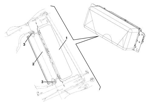
SIDE BAG MODULE
The figure below shows a view
of assembly.1 - Seat cover
2 - Side Air Bag module (Side Bag)
3 - Supply cable
SPECIFCATIONS
To provide maximum protection
in the event of side impacts, there are two side Air Bag modules
for the front seats installed on the seat squabs, under the cover.This conformation is considered to be the
most efficient as it always enables the Air Bag to be in the optimum
position in relation to the occupant, irrespective of the seat adjustment
or size of the occupant.The Side Bag offers protection for the chest
area and, together with the door panels, guarantees the protection
of critical areas of the body such as the ribs and the abdomen.
Its position on the seat guarantees maximum effectiveness, irrespective of
the position of the actual seat even if the occupant is not seated
correctly, as the dynamics of opening of the bag minimises the risk
of damage to the body caused by the impact with the bodyshell. | Do not put covers on the front
seat squabs. |
| Do not wash the seat squab with
water or pressurised steam. |
COMPOSITION
The side Air Bag module consists
of a metal container holding the gas generator and a nylon bag with
a volume of about 11 litres.The module's container has a card cover
which, with the seat squab cover fitted, line up with easy-open
sections of seam on the outside of the seat cover.The module is connected to the electrical
system by means of two cables with a yellow coloured outer casing
housed, together with the earth connecting cable for the seat, in
a protective duct, secured to the seat structure. The two cables
end in a yellow connector. The connectors are anchored on a removable
mount on the seat base.
OPERATION
The gas generator is electrically
activated by a signal coming from the electronic control module.
Following this siganl, a pyrotechnic charge is triggeed which causes
the gases contained in the generator to expand. The gases expand,
coming out of specific holes, and inflate the bag. The inflation
of the bag causes the backrest cover easy-open sections of seam
to give, allowing the correct escape of the bag itself. When fully
inflated, the bag is in the optimum position for carrying out its function
of protecting the occupant. The bag deflates immediately through
the presence of two breather openings. | No operations, other than removing
and refitting the seat from the vehicle, can be carried out on a
seats equipped with a Side Bag. It is strictly prohibited to dismantle
seats fitted with Air Bags. |
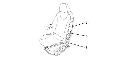
CURTAIN SIDE AIR BAG MODULE (WINDOW BAG)
General view1 - Connector
2 - Gas generator
3 - Bag retaining bands
4 - Bag
5 - Retaining harness
SPECIFCATIONS
The Window Bags are activated
together with the Side Bags and place themselves between the occupant
and the vehicle preventing contact between the head and highly dangerous
objects such as the windows, pillars, etc.Since they extend from the front pillar
to the luggage compartment, Window Bags protect both the front and
rear passengers; The 'curtain' solution is optimum thanks to the
extensive surface and its capacity to support itself even in the
absence of support;The permeability of the bag ensures that
protection is maintained even in 'long' impact situations such as
overturning.
COMPOSITION
The Window Bag module consists of:
- a gas generator secured by appropriate mounting to the
car's rear pillar;
- a permeable fabric flexible tube, secured by a band
to the gas generator, which diffuses the gas evenly along the whole length
of the bag;
- a bag, with a volume of about 34 litres, secured to
the gas generator together with the flexible pipe, is made of a
nylon permeable fabric and is folded inside a containing sleeve.
The bag is designed so that, when inflated, it correctly absorbs the
energy of the impact, holding the heads of the occupants an appropriate
distance from the impact zone. After inflation, the gas deflates
immediately through the porous fabric.
- plastic easy-open clamps for securing the bag to the
ceiling longitudinal member;
- a retaining strap, fastened to the front pillar, which
holds the inflated bag in position;
OPERATION
The gas generator is electrically
activated by a signal coming from the electronic control module.
Following this siganl, a pyrotechnic charge is triggeed which causes
the gases contained in the generator to expand. The gases expand
and emerge through specific holes and are distributed evenly along
the length of the bag via the flexible pipe, inflating the bag.
The increase in volume of the bag causes the retainers to break,
the sleeve seams to yield and the finishing trim to open, designed so
as to allow the bag to emerge correctly downwards. The correct unfolding
of the bag is ensured by a retaining strap, present at the front
end of the bag. After completion, the bag is in the optimum position
for carrying out its function of protecting the occupant. After
inflation, the bag deflates immediately because of the permeability
of the fabric.
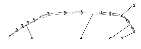
CLOCK SPRING
The diagram below illustrates
the clock spring1 - Electrical connection for Air Bag first stage
2 - Electrical connection for Air Bag second stage
3 - Steering wheel electrical functions cable
4 - Watch spring
SPECIFCATIONS
The clock spring makes it possible
to transfer the electrical signal for the controls on the steering
column (horn and other optional services) and connect the AIR-BAG
module with danger of breaking.The device, consisting of two plates is
secured by means of the lower plate to the stalk unit, and is joined
to the steering wheel by means of specific recesses on the upper
plate. The module connecting cables and the horn buttons are wound around
inside the two plates allowing them to follow the movement of the
steering wheel.Clock spring PINOUT below:| PIN | PIN FUNCTION |
|---|
| 1 | Negative signal from horn control button |
| 2 | N.C. |
| 3 | B-CAN B |
| 4 | B-CAN A |
| 5 | Supply controlled by the ignition |
| 6 | Earth |
| 7 | N.C. |
| 8 | N.C. |
| 9 | Air Bag level 2 (+) |
| 10 | Air Bag level 2 (-) |
| 11 | Air Bag level 1 (-) |
| 12 | Air Bag level 1 (+) |
COMPOSITION
The clock spring on the steering
wheel has three cables, two of which is for connecting the Air Bag
module (first and second stage) and one of which is for connecting
the steering wheel electrical functions (horn, radio controls).On the upper plate, steering wheel side,
there is a ring which automatically blocks the rotation between
the two plates when the device is removed from the steering wheel.The new device is supplied with a safety
key for transport, to be removed before fitting.
OPERATION
Inside the two plates, the connecting
cables for the Air Bag module and the various electrical functions
are wound in a spiral, with a sufficient number of coils to follow
the steering wheel's rotations. The upper plate rotates by means
of the recesses present inside the locking ring which fit in the
seating on the steering wheel hub. In the working position, the
steering wheel presses on the ring, freeing it from the recesses,
thus unlocking the rotation between the two plates. When the steering
wheel is removed, pushed by a spring, it blocks the rotation between
the two plates. This function prevents the top plate, no longer locked
to the steering wheel, from turning freely and causing the sprial
inside the device to unwind or wind and then possibly break.In operations involving the removal
of the steering wheel and the device, the following must be observed:
- always operate with the wheels lined up straight;
- lock the two plates with a band, for safety reasons,
before removing the device from the steering column switch unit.
| If for any reason the upper plate
rotates in relation to the lower plate so much that the original
position cannot be identified with absolute certainly, the clock
spring MUST be replaced. |
FRONT IMPACT SATELLITE SENSOR
Location of front impact sensor
ECS
SPECIFCATIONS
The ECS Early Crash Sensor additional
sensor is located near the bonnet lock; it assists the electronic
control unit to anticipate the intervention of the Air Bags compared
with a conventional system so that the activation of the Air Bags
is completed before the occupant even starts moving forwards towards
the steering wheel or the dashboard.In addition, this sensor detects underbody
impacts or stresses for which the activation of the Air Bags is
not required as there is no risk to the occupants.
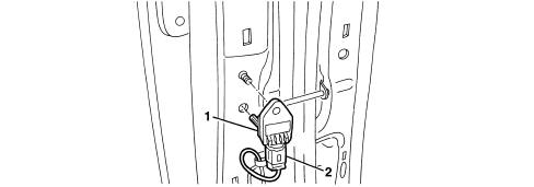
SIDE IMPACT SATELLITE SENSORS
Location of side impact sensor1 - Side impact satellite sensor
2 - Connecting connector
SPECIFCATIONS
Apart from the Air Bags, the
side protection system also comprises the electronic control module
which ensures correct operation. To measure the acceleration resulting
from a side impact, there are two satellite sensors installed in
the side pillars, containing an accelerometer.
OPERATION
If the acceleration value measured
by the sensor in question causes a particular threshold to be exceeded,
this information is compared with the measurement obtained from
the safing sensor contained in the Air Bag system's electronic control
unit. If the values measured are consistent, the control unit causes
the activation of the Air Bags and the Window Bags on the side affected
by the impact.
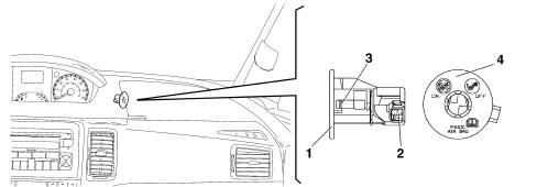
PASSENGER AIR BAG DISABLEMENT KEY SWITCH
A switch with a key in the upper
dashboard compartment, passenger side, allows the user to deactivate
the passenger Air Bag allowing the possibility of fitting a rear-facing
child seat on the front seat without any risk.
OPERATION
The switch, which can be operated
using the ignition key, makes it possible to enable (ON) and disable
(OFF) the passenger Air Bag module.In this case the control unit excludes the
activation of the passenger Air Bag, but not the operation of the
pretensioner (only with the seat belt fastened) and the side bags.
This is because if there is a passenger present but the switch has
been incorrectly left OFF, the Air Bag will not be activated only
the pretensioner.Deactivation is indicated by a warning light
on the control panel.
COMPOSITION
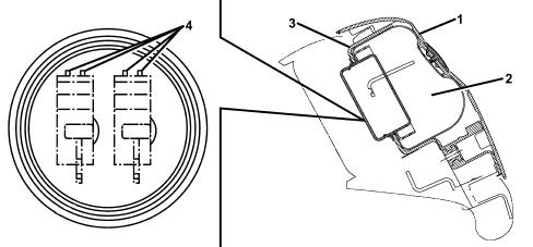
The diagram shows a view of the
assembly.1 - Casing
2 - Switch
3 - Key barrel
4 - Plate
COMPOSITION
The unit consists of a casing
containing the switch, a key barrel inserted in the casing and held
by a clip and a plate which indicates the position assumed by the
switch (ON or OFF).Any faults in the switch are indicated by
the Air Bag system fault warning light coming on.The electronic control unit checks the status
of the switch during the normal diagnostic procedure at Key On (four
seconds).If the recognised state is OFF, it excludes
the module from possible activation, memorises the corresponding
signal and causes the warning light in the instrument panel to
come on.If the recognised state is ON, after the
four seconds of the diagnostic procedure the warning light flashes
for a further four seconds and then goes out.In the case of faults in the switch,
the system ensures the following:
- it does not activate the passenger module
- it causes the Air Bag fault warning light to come on
- it causes the passenger Air Bag disabled warning light
to come on
- it memorises the state of deactivation.
| Do not operate the switch with
the ignition key in the ON position (e.g. by using the second key).
In this case the electronic control unit would memorise a fault,
indicating it by switching on the Air Bag fault warning light and deactivating
the module. |
SPECIFCATIONS
The pretensioners are pyrotechnic
devices, electrically activated by a signal coming from the electronic
control unit, integrated in the front seat belt winder. The same
logic that controls the Air Bags controls the activation of the
seat belt pretensioners.The pretensioners are designed to recover
any seat belt slack in order to keep the occupant against the backrest
during the initial moments of the impact, reducing movement inside
the passenger compartment.The belts are also fitted with load limiters
which decrease the force transmitted from the belts to the chest:
the level of force at which the limiters intervene is such as to
considerably reduce the risk of fractures of the shoulders and ribs
even in persons with more brittle bones (e.g. the elderly).
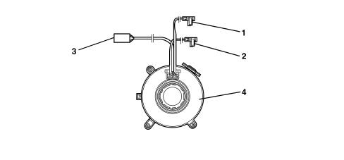
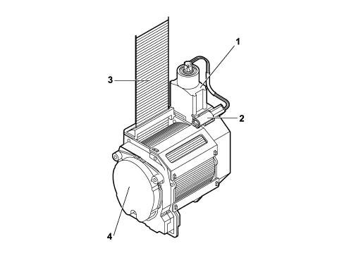
OPERATION
The diagram below shows the pretensioner
mechanism1 - Gas generator
2 - Electrical connector
3 - Belt
4 - Reel
OPERATION
The moment the vehicle deceleration
is sufficiently high, detected by the system accelerometers, the
electronic sensor located in the control unit sends a signal which
primes the pyrotechnic charges for the gas generators (6). The burning
of the propellant produces a chemical reaction creating inert gas
whose pressure creates a force which thrusts the rack pinion upwards,
changing the rotary movement of the check to the opposite direction
to the unwinding of the belt, rewinding it by a few centimetres. | Once the pretensioners have intervened,
the seat belts remain locked and must be replaced. |
AIR BAG SIGNALLING WARNING LIGHTS
During starting, key in key-on
position, the Air Bag system fault warning light (red) comes on
for about four seconds (initial self-test stage) and then goes out.
If the control unit detects a fault in the warning light, it memorises
the corresponding fault code. If no faults are detected in the system
at key-on, and there are no fault conditions in the fault memory,
the warning light goes out after four seconds of self-test, otherwise
it stays on.The warning light remains on or comes
on, during the normal operation of the vehicle, in the following
cases:
- the control unit detects a fault in the Air Bag system;
- the control unit detects an impact with activation of
the system;
- the control unit detects a fault in the actual warning
light connection circuit.
As a result of an impact with the intervention
of only the pretensioners or side Air Bags, the warning light stays
on until the system's operating conditions are restored (replacement
of the component concerned and rest of the control unit using the EXAMINER).if the impact causes the intervention of
the front Air Bag modules, the warning light stays on permanently,
and the control unit cannot be reset (in this case the control unit
must be replaced).If internal operating faults arise during
the control unit's operating life, and these faults cannot be reset
by the EXAMINER, they are indicated by the warning light staying
on permanently.With the key at the key-on position, the
passenger's Air Bag disabled warning light (yellow) comes on for
about four seconds (initial self-test stage) and flashes for 4 secs.
afterwards. If the control unit detects a fault in the warning light,
it memorises the relevant fault code, switches on the fault warning
light and keeps the passenger's Air Bag module disabled. Restore
the system's operation using the EXAMINER, in the same way as for
the fault warning light. | The passenger's module MUST be
disabled only using the ignition key (ignition switch in OFF position).
(DO NOT USE a second ignition key for disablement). |