169001654 - 2720C11 REAR DIFFERENTIAL UNIT - OVERHAUL WITH THE DIFFERENTIAL DETACHED (SUV)
| Description | Code | Function | |
|---|---|---|---|
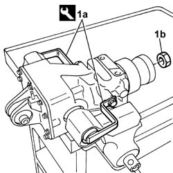
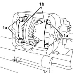
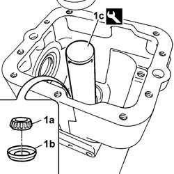
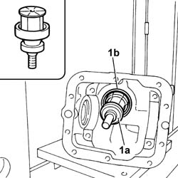
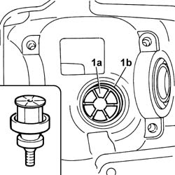
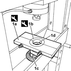
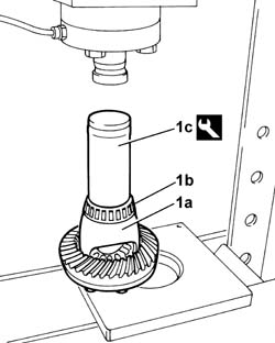
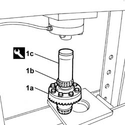
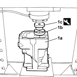
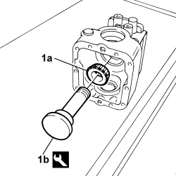
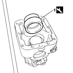
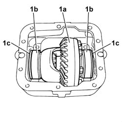
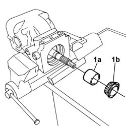
| 1a | Counter-torque | 1.871.006.000 | Joint retainer |
| Description | Code | Function | |
|---|---|---|---|
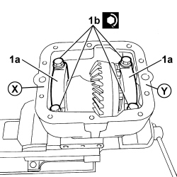
| 1b | Spanner | 1.871.005.400 | Loosen/tighten collar |
| Description | Code | Function | |
|---|---|---|---|
| 1c | Reaction bush | 1.871.005.100 | Reaction |
| Description | Code | Function | |
|---|---|---|---|
| - | Counter-torque | 1.871.006.000 | Joint retainer |
| Description | Code | Function | |
|---|---|---|---|
| - | Blade | 1.870.718.000 | Cut the sealant strip |
| Mark the original lh and rh position of the mounting brackets before removal. |
| Take the GREATEST care during the operation described below. |
| Description | Code | Function | |
|---|---|---|---|
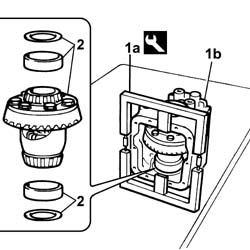
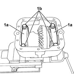
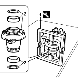
| 1a | Divider | 1.871.006.300 | Rear differential case divider |
| Mark the original position of the spacers before removal. |
| Description | Code | Function | |
|---|---|---|---|
| - | Divider | 1.871.006.300 | Rear differential case divider |
| Description | Code | Function | |
|---|---|---|---|
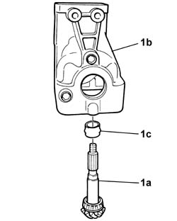
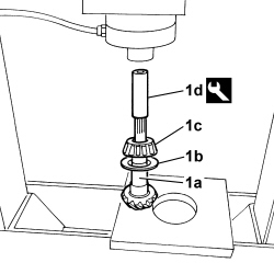
| 1a | Reaction plate | 1.870.845.000 | Reaction plate |
| Description | Code | Function | |
|---|---|---|---|
| 1b | Extractor | 1.871.006.100 | Bearing extractor |
| Description | Code | Function | |
|---|---|---|---|
| 1c | Extractor | 1.871.004.500 | Bearing extractor |
| Description | Code | Function | |
|---|---|---|---|
| 1a | Reaction plate | 1.870.845.000 | Reaction plate |
| Description | Code | Function | |
|---|---|---|---|
| 1b | Reaction plate | 1.870.845.000 | Reaction plate |
| Description | Code | Function | |
|---|---|---|---|
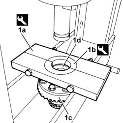
| 1a | Reaction plate | 1.870.845.000 | Reaction plate |
| Description | Code | Function | |
|---|---|---|---|
| 1b | Reaction plate | 1.870.845.000 | Reaction plate |
| Description | Code | Function | |
|---|---|---|---|
| 1c | Fitting tool | 1.871.004.400 | Fitting tapered bearings |
| Description | Code | Function | |
|---|---|---|---|
| 1c | Fitting tool | 1.870.424.000 | Fitting tapered bearings |
| Description | Code | Function | |
|---|---|---|---|
| 1c | Fitting tool | 1.870.424.000 | Fitting bearing races |
| Description | Code | Function | |
|---|---|---|---|
| 1c | Fitting tool | 1.871.005.800 | Fitting bearing races |
| Description | Code | Function | |
|---|---|---|---|
| 1b | Dummy pinion | 1.871.005.000 | Template |
| Description | Code | Function | |
|---|---|---|---|
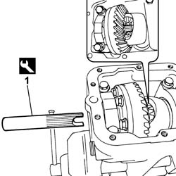
| 1 | Dummy pinion gauge | 1.871.004.900 | Template |
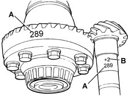
| The value VP can be either positive or negative.The spacers available vary from a minimum of 0.51 mm to a maximum of 1.40 mm in increments of 0.05 mm. |
| Description | Code | Function | |
|---|---|---|---|
| - | Dummy pinion gauge | 1.871.004.900 | Template |
| Description | Code | Function | |
|---|---|---|---|
| - | Dummy pinion | 1.871.005.000 | Template |
| Take the GREATEST care during the operation described below. |
| Description | Code | Function | |
|---|---|---|---|
| - | Divider | 1.871.006.300 | Rear differential case divider |
| Description | Code | Function | |
|---|---|---|---|
| - | Divider | 1.871.006.300 | Rear differential case divider |
| To determine the total size of the two spacers it is advisable to start the check using the old spacers and, if necessary, increasing or decreasing the size to produce the correct rolling torque. The shims available go from a minimum of 1.91mm to a maximum of 3.00 mm. |
| Subject | Value | |
|---|---|---|
| - | Differential unit rolling torque (daNm) | 0.83 -3,32 |
| - | Differential unit rolling torque (Ncm) | 83 - 332 |
| Description | Code | Function | |
|---|---|---|---|
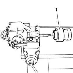
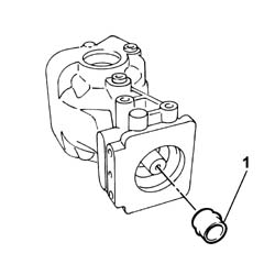
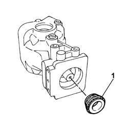
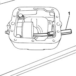
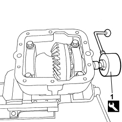
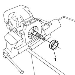
| 1 | Counter-torque | 1.870.789.000 | Counter-torque |
| Take the GREATEST care during the operation described below. |
| Description | Code | Function | |
|---|---|---|---|
| - | Divider | 1.871.006.300 | Rear differential case divider |
| Description | Code | Function | |
|---|---|---|---|
| - | Divider | 1.871.006.300 | Rear differential case divider |
| Description | Code | Function | |
|---|---|---|---|
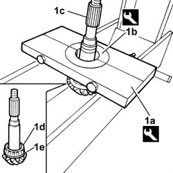
| 1d | Fitting tool | 1.871.004.500 | Bearing fitting tool |
| Value daNm | Fastening | Component | Ø | |
|---|---|---|---|---|
| - | 20 | Ring nut | Bevel pinion | - |
| Description | Code | Function | |
|---|---|---|---|
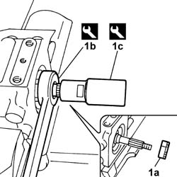
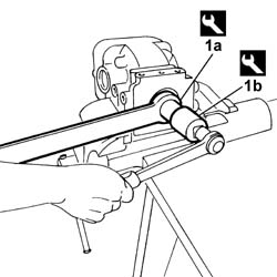
| 1a | Spanner | 1.871.005.400 | Loosen/tighten collar |
| Description | Code | Function | |
|---|---|---|---|
| 1b | Reaction bush | 1.871.005.100 | Reaction |
| Description | Code | Function | |
|---|---|---|---|
| - | Spanner | 1.871.005.400 | Loosen/tighten collar |
| Description | Code | Function | |
|---|---|---|---|
| - | Reaction bush | 1.871.005.100 | Reaction |
| Description | Code | Function | |
|---|---|---|---|
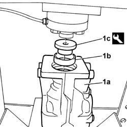
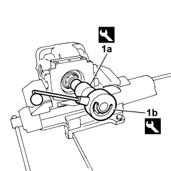
| 1a | Reaction bush | 1.871.005.100 | Reaction |
| Description | Code | Function | |
|---|---|---|---|
| 1b | Counter-torque | 1.870.789.000 | Counter-torque |
| Alternate a gradual closing stage for the ring nut fixing the bevel pinion with a check on the rolling torque until the value indicated is reached. |
| Subject | Value | |
|---|---|---|
| - | Bevel pinion rolling torque (Nm) | 2,3 - 3,4 |
| - | Bevel pinion rolling torque (Nm) | 230 - 340 |
| Take the GREATEST care during the operation described below. |
| Description | Code | Function | |
|---|---|---|---|
| - | Divider | 1.871.006.300 | Rear differential case divider |

| Description | Code | Function | |
|---|---|---|---|
| - | Divider | 11.871.006.300 | Rear differential case divider |
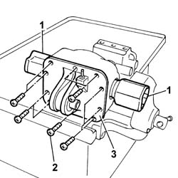
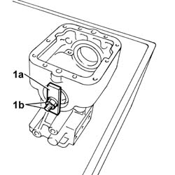
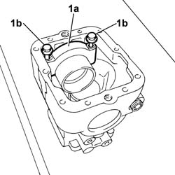
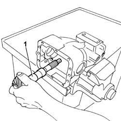
| The U-bolts retaining the differential unit should be removed ensuring that they are correctly positioned. |
| Value daNm | Fastening | Component | Ø | |
|---|---|---|---|---|
| 1b | 4.1 - 6.1 | Bolt | - | - |
| Description | Code | Function | |
|---|---|---|---|
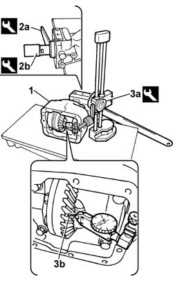
| 2a | Spanner | 1.871.005.400 | Loosen/tighten collar |
| Description | Code | Function | |
|---|---|---|---|
| 2b | Reaction bush | 1.871.005.100 | Reaction |
| Description | Code | Function | |
|---|---|---|---|
| 3a | Dial gauge | 1.871.005.300 | Measuring clearance |
| Subject | Value | |
|---|---|---|
| - | Clearance between ring gear and bevel pinion (mm) | 0.10 - 0.18 |
| If the value measured was below the nominal figure, increase the size of the shim on side X and decrease the size of the shim on side Y by the same value as it was increased on side X. If the value measured was above the nominal figure, increase the size of the shim on side Y and decrease the size of the shim on side X by the same value as it was increased on side Y. The total thickness of the two shims should not vary from the figure set previously. |
| Description | Code | Function | |
|---|---|---|---|
| - | Spanner | 1.871.005.100 | Reaction |
| Description | Code | Function | |
|---|---|---|---|
| - | Reaction bush | 1.871.005.400 | Loosen/tighten collar |
| Description | Qty. | Component | Type | Classification | |
|---|---|---|---|---|---|
| - | Rubber Wacker | - | - | T209 | Sealant |
| Value daNm | Fastening | Component | Ø | |
|---|---|---|---|---|
| - | 3.8 - 4.5 | Bolt | - | - |
| Description | Code | Function | |
|---|---|---|---|
| - | Fitting tool | 1.871.006.200 | Oil seal fitting tool |
| Description | Code | Function | |
|---|---|---|---|
| - | Fitting tool | 1.871.005.900 | Oil seal fitting tool |
| Description | Code | Function | |
|---|---|---|---|
| - | Counter-torque | 1.871.006.000 | Joint retainer |
| Value daNm | Fastening | Component | Ø | |
|---|---|---|---|---|
| - | 12 - 15 | Nut | - | - |
| Description | Code | Function | |
|---|---|---|---|
| - | Counter-torque | 1.871.006.000 | Joint retainer |