2752660 - 2110A10 manual gearbox and differential - r + r
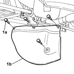
 | Name | Connector |
|---|---|---|
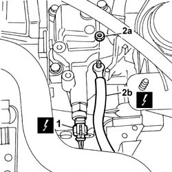
| 1 | Reversing lights switch | I20 |
| Name | Connector |
|---|---|---|
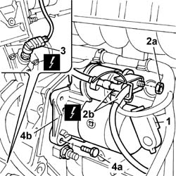
| 2b | Battery earth on engine | C2 |
| Name | Connector |
|---|---|---|
| 2b | Starter' motor | A20A |
| Name | Connector |
|---|---|---|
| 2b | Starter' motor | A20B |
| Name | Connector |
|---|---|---|
| 2b | Starter' motor | A20C |
| Name | Connector |
|---|---|---|
| 3 | Speedometer sensor | K84 |
 | Name | Country |
|---|---|---|
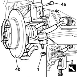
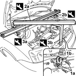
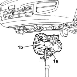
| 2 | Extractor | 1.871.000.700 |
| Name | Country |
|---|---|---|
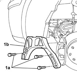
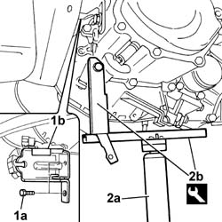
| 2a | Crossmember | 1.870.595.000 |
| Name | Country |
|---|---|---|
| 2b | Support mountings | 1.870.650.000 |
| Name | Country |
|---|---|---|
| 3a | Crossmember | 1.860.851.003 |
| Name | Country |
|---|---|---|
| 3b | Vertical support | 1.871.001.300 |
| Secure the engine, using the special hooks and brackets/chains taking great care to ensure that the engine is properly balanced. |
| Name | Country |
|---|---|---|
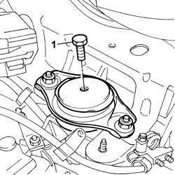
| 2b | Gearbox mount | 1.860.873.000 |
| To facilitate centring the pins on the engine and the gearbox shaft and the clutch driven plate, move the gearbox-differential unit slightly. |
 | Fastening | Component | Ø | Value(daNm) |
|---|---|---|---|---|
| - | Bolt | MANUAL GEARBOX | M12 x 1.25 | (below gearbox) 8 |
| Fastening | Component | Ø | Value(daNm) |
|---|---|---|---|---|
| - | Nut | MANUAL GEARBOX | M12 x 1.25 | (below gearbox) 8 |
| Name | Country |
|---|---|---|
| - | Gearbox mount | 1.860.873.000 |
| Fastening | Component | Ø | Value(daNm) |
|---|---|---|---|---|
| - | Bolt | MANUAL GEARBOX | M12 x 1.25 | (upper gearbox) 8 |
| Fastening | Component | Ø | Value(daNm) |
|---|---|---|---|---|
| - | Bolt | POWER UNIT GEAR BOX END RIGID MOUNT | M10 x 1.25 | (Gearbox side) 5 |
| Fastening | Component | Ø | Value(daNm) |
|---|---|---|---|---|
| - | Bolt | POWER UNIT GEAR BOX END RIGID MOUNT | M12 x 1.25 | (Flexible block side) 8 |
| Name | Country |
|---|---|---|
| - | Crossmember | 1.870.595.000 |
| Name | Country |
|---|---|---|
| - | Support mountings | 1.870.650.000 |
| Name | Country |
|---|---|---|
| - | Crossmember | 1.860.851.003 |
| Name | Country |
|---|---|---|
| - | Vertical support | 1.871.001.300 |
| Fastening | Component | Ø | Value(daNm) |
|---|---|---|---|---|
| - | Nut | FRONT HUB STEERING KNUCKLE. | M10 x 1.25 | 7.5 |
| Fastening | Component | Ø | Value(daNm) |
|---|---|---|---|---|
| - | Nut | ADJUSTABLE STEERING LINKS | M10 x 1.25 | 4 |
| Name | Connector |
|---|---|---|
| - | Speedometer sensor | K84 |
| Fastening | Component | Ø | Value(daNm) |
|---|---|---|---|---|
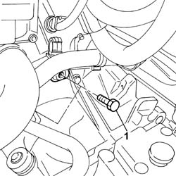
| - | Bolt | STARTER MOTOR | M8 | 2.7 |
| Name | Connector |
|---|---|---|
| - | Starter' motor | A20A |
| Name | Connector |
|---|---|---|
| - | Starter' motor | A20B |
| Name | Connector |
|---|---|---|
| - | Starter' motor | A20C |
| Fastening | Component | Ø | Value(daNm) |
|---|---|---|---|---|
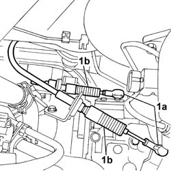
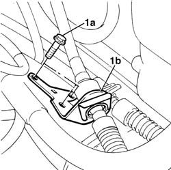
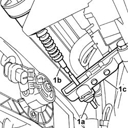
| - | Bolt | GEAR ENGAGEMENT ASSEMBLY CABLE | M8 | 3 |
| Name | Connector |
|---|---|---|
| - | Reversing lights switch | I20 |
| Name | Connector |
|---|---|---|
| - | Battery earth on engine | C2 |