198001485 - 5505 INSTRUMENT/GAUGE ELECTRICAL CIRCUITS
Structure of electrical/electronic system
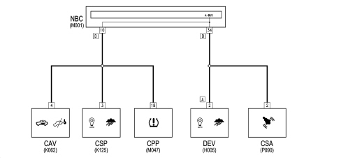
The electrical equipment on this vehicle uses the "NANO F.L.ORE.N.C.E." structure developed specifically to incorporate the most up to date electronic functions in an optimum manner.This structure makes up the car''s nervous system, directly controlling all the bodywork functions (access control, visibility, on board information, comfort, etc.) and communicates with the various chassis and power unit subsystems, optimising the system''s fault diagnosis, reliability, weight and cost.A further advantage compared with traditional systems is simplified installation, thanks to a reduced number of control units (the same number of functions are offered to customers) and power and signal connections, through the extensive use of serial communication networks (3 CAN twin wire communication networks, 1 single wire LIN subnetwork, 1 A-BUS single wire subnetwork).Power distribution takes place by means of four junction units and relay/fuse boxes, connected to the control elements (static actuators and relays). These control units also act as an interconnection for the wiring and as an electrical distributor to ensure the maximum level of electrical protection and the minimum degree of wiring complexity.Electronic components
It is a simplified version of the previous "MINI FLORENCE" system: the structure has been simplified to manage a greater number of functions with the Body Computer.The main electronic components managed by the NANO F.L.ORE.N.C.E. structure are listed below:| Electronic components | Wiring diagram code |
|---|---|
| Body Computer Node | M001 |
| Engine Management Node | M010 |
| Robotised Gearbox Node | M054 |
| Electric steering node | M086 |
| Volumetric Sensors Control Unit | K062 |
| Anti-theft Alarm Control Unit | P090 |
| Instrument Panel Node | E050 |
| Info-Telematic Node | P020 |
| Radio Receiver Node | P020 |
| Bluetooth Control Unit Node | M162 |
| Steering wheel interface module | H005 |
| Dusk and rain sensor | P155 |
| Braking Node | M050 |
| Driver''s Seat Position Node | H066 |
| Passenger''s Seat Position Node | H067 |
| Yaw Sensor Node | K074 |
| Air Bag Node | M060 |
| Climate Control Node | M070 |
| Tyre Pressure Control Unit | M047 |
| Parking Sensor Node | M084 |
| Left Headlamp Control Unit | F010 |
| Right Headlamp Control Unit | F011 |
Electric power control unit (fuse boxes)
There is a wired control unit in the luggage compartment (CVB) and three fuse/relay boxes built using sheared circuit technology:- Dashboard Junction Unit (CPL) in dashboard- Engine Compartment Junction Unit (CVM) in engine compartment- Battery and Optional Fuses Control Unit (CBA, CFO) above the battery| Fuse boxes | Wiring diagram code |
|---|---|
| Battery Control Unit CBA | B099 |
| Optional Fuses Control Unit CFO | B098 |
| Engine Compartment Control Unit CVM | B001 |
| Dashboard Control Unit CPL | B002 |
| Luggage Compartment Control Unit CVB | B045 |
Network structure
The completed structure comprises three CAN communication networks connected by a gateway for transferring shared information:- C-CAN network (low speed: 500 kbit) for dynamic vehicle control- B-CAN network (high speed: 50 kbit) for managing bodywork functions- CAN network for multimedia functions.The gateway for communication between the C-CAN and B-CAN is located in the Body Computer.The diagnosis of the nodes connected to the B-CAN network is carried out via the CAN, whilst the diagnosis for those connected to the C-CAN network is carried out by means of the specific K lines (5 ISO serial lines for diagnosis).The K lines and the B-CAN network flow into the EOBD diagnostic connector centrally located on the Body Computer.For right-hand drive versions there is a diagnosis connector not connected to the Body Computer. It is located to the right of the steering wheel in an easily accessible position.In this configuration the Body Computer is on the left side of the vehicle and therefore not very accessible as it is behind the glove compartment.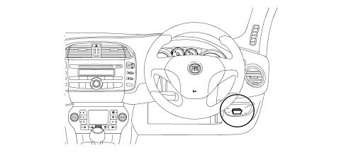
Replacing and initializing network nodes
Some of the CAN network nodes are programmed with default settings which the customer will discover on acquiring the vehicle.The nodes storing this information are the:- Body Computer;- Instrument Panel Node;- Bluetooth Control Unit Node;- Climate Control System Control Unit;- Air Bag Node| If the Body Computer is being replaced, an identical copy of the Body Computer must be obtained from the Parts Dept as a V.O.R. order supplying the vehicle chassis number: this copy will contain all the default settings entered when the vehicle was new which are stored in the Parts Dept. database under the vehicle chassis number. |
| If the other nodes mentioned above are being replaced, the Parts Dept. will send a pristine component: once fitted, the initial default data must be transferred to it by carrying out the PROXI ALIGNMENT procedure using the Examiner. |
CONTROL UNIT ON BATTERY (CBA)
This connects the battery terminal to the starter motor lead and to the first level power fuses that protect the supply for the engine compartment control unit (CVM), the dashboard control unit (CPL), the luggage compartment control unit (CVB), where the second level protective fuses are located.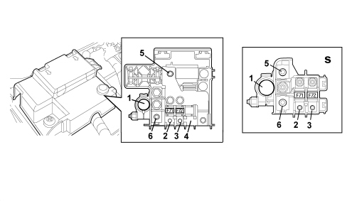
| CODE | Fuses in control unit (CBA) | Amperage |
|---|---|---|
| F71 | for dashboard control unit (CPL) | 70A |
| F72 | 70A | |
| F73 | wiring | _ |
| On some versions there is a simplified version of the CBA (s) that is smaller and takes up less room |
OPTIONAL FUSES CONTROL UNIT
Next to the CBA there are two additional fuses for versions which have an additional heater: F74 (30A) and F76 (50A).ENGINE COMPARTMENT CONTROL UNIT (CVM)
Electro-mechanical control unit including fuses (Maxi and Mini), relays and circuits for connecting the front wiring and radiator pre-wiring.This wiring is connected to the control unit by fixed couplings. There is a chamber under the protective cover for housing any further connectors/relays/fuses.There is a fastening on the lower cover for sealed fuse holder connectors (maxi and auto type).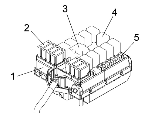
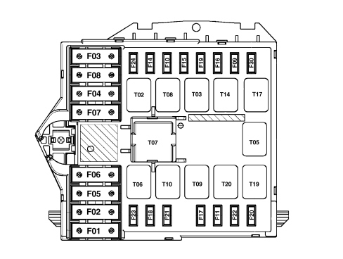
| CODE | COMPONENT | AMP. | TYPE |
|---|---|---|---|
| F-1 | Braking system control unit | 40 | MAXI |
| F-2 | Dashboard control unit | 50 | MAXI |
| F-3 | Ignition switch | 20 | MAXI |
| F-4 | Selespeed gearbox control unitHeadlamp washer electric pump 1.4 16v | 30 | MAXI |
| F-5 | Glow plug preheating control unit | 50 | MAXI |
| F-6 | Engine cooling fan (low speed/one speed) | 20/30/40 (*) | MAXI |
| F-7 | Engine cooling fan (high speed) | 40/50 (*) | MAXI |
| F-8 | Passenger compartment cooling fan | 30 | MAXI |
| F-9 | Fog light, right cornering light | 7,5 | mini |
| F-10 | Horn | 10 | mini |
| F-11 | Engine management system secondary loads | 15 | mini |
| F-14 | Right main beam headlamp | 7,5 | mini |
| F-15 | Left main beam headlamp | 7,5 | mini |
| F-16 | Engine management control unit, gearbox control unit | 7,5 | mini |
| F-17 | Engine management control unit | 10 | mini |
| F-18 | Engine management control unit, gearbox control unit | 10 | mini |
| F-19 | Air conditioning compressor | 7,5 | mini |
| F-20 | Headlamp washer electric pump | 20 | mini |
| F-21 | Fuel pump in tank | 15 | mini |
| F-22 | Engine management system primary loads | 15 / 20 (*) | mini |
| F-23 | Braking system control unit | 30 | mini |
| F-24 | Electric steering control unit | 7,5 | mini |
| F-30 | Fog light, left cornering light | 7,5 | mini |
| CODE | COMPONENT | AMP. | TYPE |
|---|---|---|---|
| T02 | Main beam headlamp | 20 | micro |
| T03 | Horn | 20 | micro |
| T05 | Air conditioning compressor | 20 | micro |
| T06 | Engine cooling fan (low speed/one speed) | 30 | micro |
| T07 | Engine cooling fan (high speed) | 50 | MAXI |
| T08 | Passenger compartment cooling fan | 30 | micro |
| T09 |
| ... DATA ERROR - CROPPED TEXT | Ошибка данных - Текст обрезан ... |
|---|