199000630 - 5040 AIR CONDITIONING CASING AND COMPONENTS
INTRODUCTION
The climate control system fitted to the vehicle is used to alter the environmental properties of air taken into the passgenger compartment (temperature and humidity), allowing the demisting of the glass surfaces and preventing the intake of pollutant substances making the environment in the passenger compartment more healthy.The air conditioning system is a comfort factor that contributes to improving the physiological wellbeing conditions of the occupants of the vehicle.Climate control system components
The climate control system components are illustrated in the diagram below.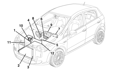
Operating principle
The aim of refrigeration equipment is to absorb heat from an environment. In order to do this an air conditioner has recourse to certain fluids (known as refrigerants) capable of cooling down (lowering their temperature) and changing state (from liquid to gas) when they are subject to a large drop in pressure, expanding. They are therefore capable of absorbing heat from the environment. When the temperature increases thereby also increasing the pressure, they change state, another time, from gas to liquid, and condense.The first problem is therefore to liquefy this gas which can be achieved simply by bringing it to a temperature below that of evaporation (or boiling) which, as has already been stated, is -26°C at atmospheric pressure for R134a.In order for this to be achieved at ambient temperature which, in our case, may be rather high (in the engine compartment), it is necessary to increase the evaporation point of the gas so that it remains liquid until the moment it is made to expand to produce the desired refrigerant effect.To raise the boiling point of the gas its pressure must be increased, at the same time, decreasing the temperature.In order for this to take place the system requires a certain amount of power. This power, supplied by the compressor, is subtracted from the power produced by the engine.The operating principle of the refrigerant cycle phases in the air conditioning system for a motor vehicle can be summed up as follows.The gaseous R134a refrigerant is drawn in by the compressor at a pressure of between 0.5 and 2 bar and is compressed at a value of between 10 and 17 bar. The boiling point at these pressures is around 60 °C.This fluid, heated by the compression stage at 80 -100 °C, always in a gaseous state, in the compressor where, through the effect of the cooling air flow (produced by the vehicle moving forward or through the action of the fan) that passes through, reaches condensation point, changing at high pressure to a liquid state.Later on the refrigerant passes through a filter which has three functions: to trap the impurities, absorb the dampness contained in the circuit and work as a reserve reservoir for the actual refrigerant.The refrigerant reaches the expansion valve, where it is introduced into the evaporator where the pressure is around 1.5 atm. (1.52 bar). At this pressure the liquid/vapour system saturated with the refrigerant fluid is in equilibrium at a temperature of about -7 °C. At the same time, the air that passes through the evaporator (through the action of a fan), being at a considerably higher temperature than the refrigerant fluid it contains, causes it to boil and evaporate completely by imparting heat. On cooling, the air deposits some of the dampness it contains on the evaporator fins in the form of droplets which are collected in a chamber and drained off from the vehicle.The cooled and dehumidified air is sent inside the vehicle. The refrigerant is drawn in by the compressor again at the evaporator outlet, thereby giving rise to a new cycle once again.The route of the refrigerant fluid can be summarized as follows:- In the compressor the fluid coming from the evaporator is gaseous (temp. -5, -7°C, pressure 0.5 2 bar). Compression phase - the gaseous fluid is overheated (temp. 80 -100 °C, pressure 10 17 bar).- Condensator - Compression phase: the fluid gives off heat to the outside, cools down and returns to a liquid state (temp. 40 60°C, pressure 10 17 bar).- Thermostatic expansion valve - Expansion phse - the fluid loses pressure (0.5 2 bar, possibly even 3 bar) becomes a gas + liquid mixture; the temperature is low, typical of air conditioning.- Evaporator - Evaporation phase - the fluid becomes completely gaseous because the hot air driven by the fan finds itself at a higher temperature than the refrigerant fluid and causes it to boil and evaporate completely giving off heat. The temperature is low, typical of air conditioning (pressure 0.5 2 bar).Types of system
This vehicle can be equipped with different climate control systems for the passenger compartment:- manual climate control- dual zone automatic climate control.Manual climate control: the user sets the air temperature, distribution and flow rate and they remain like that until they are altered by the user later on.Automatic climate control (dual zone): the user can set the parameters and select automatic system management. If they so wish, the user can preseve the facility to manage the system manually.In addition, the automatic climate control system on this vehicle is the dual zone type (driver''s zone and front passenger zone), in other words the system has dual controls for the driver and the passenger and is capable of managing the settings for the two users separately, varying the air temperature and distribution parameters (the flow rate cannot be different in the zones) with a certain degree of independence.MANUAL CLIMATE CONTROL
The manual climate control system control panel is illustrated in the diagram below.
Operation
The manual air conditioning also allows the user to manage the temperature and the intake of air into the passenger compartment using the control knobs and buttons.The following parameters/functions can be altered manually:- Temperature- Distribution in 5 positions- Fan speed- Engagement of compressor- Recirculation.The transmission of the air mixing and air distribution commands from the knobs to the climate control casing takes place by means of bowden cables.The recirculation is implemented by means of an electric motor.The compressor can only be activated if one of the fan speeds is switched on.AUTOMATIC CLIMATE CONTROL
The automatic climate control system is managed by a control unit which is capable, thanks to an extremely sophisticated operating logic, of controlling the temperature in two zones of the passenger compartment heating or cooling the air to produce the desired comfort level.The climate control system automatically adjusts the following parameters/functions:- Air temperature at the driver''s/passenger side vents- Fan speed- Driver/passenger side air distribution- Engagement of compressor- Recirculation.Controls
All the non adjustment buttons are dual (ON/OFF) including the recirculation.The controls for the climate control system control unit are illustrated in the diagram below.
Climate control system control unit
The climate control system is managed automatically by an electronic control unit known as the Climate Control Node (NCL) which is charged with keeping the air climate control conditions set, and therefore desired, by the user (or users) unchanged.The NCL is connected to the vehicle''s electrical system B-CAN.The NCL is incorporated in the climate control system control panel fitted in the dashboard in the middle. The diagram illustrates the back of the control unit showing the connections to the electrical system and the connector pin out.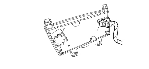
Control unit pin out
| PIN | FUNCTION |
|---|---|
| 01 | CAN L line |
| 02 | CAN H line |
| 03 | Not connected |
| 04 | Not connected |
| 05 | Fan control |
| 06 | Not connected |
| 07 | Solar sensor power supply |
| 08 | Not connected |
| 09 | Right VENT treated air temperature sensor |
| 10 | Left solar sensor analogue input |
| 11 | Analogue earth |
| 12 | Recirculation control open |
| 13 | Not connected |
| 14 | Not connected |
| 15 | Not connected |
| 16 | Not connected |
| 17 | Left FOOR treated air temperature sensor |
| 18 | Left VENT treated air temperature sensor |
| 19 | Right solar sensor analogue input |
| 20 | Right FLOOR treated air temperature sensor |
| 21 | Not connected |
| 22 | Recirculation control closed |
| 23 | Not connected |
| 24 | Shared right mixture actuator |
| 25 | Left mixture actuator feedback |
| 26 | Right mixture actuator feedback |
| 27 | Right distribution actuator feedback |
| 28 | Left distribution actuator feedback |
| 29 | Fan feedback |
| 30 | Power supply from battery |
| 31 | 5V external power supply |
| 32 | Left mixture actuator control |
| 33 | Shared right distribution actuator |
| 34 | Right distribution actuator control |
| 35 | Right mixture actuator control |
| 36 | Left distribution actuator control |
| 37 | Shared left mixture actuator |
| 38 | Shared left distribution actuator |
| 39 | Ignition-operated power supply |
| 40 | Electronic earth |
Operating logic
The control unit that manages the automatic climate control is capable of producing and maintaining the desired comfort within the two areas of the passenger compartment by controlling the following parameters and functions:- Air temperature at the driver''s/passenger side vents;- Fan speed (continuous variation);- Air distribution;- Engagement of compressor;- Recirculation.The climate control system control system is managed in such a way as to regulate the "equivalent temperature", i.e. the temperature correlated to the thermal sensation and defined by a series of parameters such as humidity, passenger compartment air flow rate, average temperature, etc.Therefore the user sets an equivalent temperature and the system acts on all the variables in its control to ensure the thermal sensation requested; for this reason the temperature in degrees centigrated measured in the passenger compartment may not coincide with the temperature shown on the display.The following parameters/functions can be altered manually:- Driver''s/passenger side temperatures- Fan speed- Distribution in 7 positions (driver / passenger).- Compressor- Defrosting/demisting function- Recirculation.Manual selections always take priority over automatic ones and are memorized until the user switches back to automatic operation.The manual setting of a function does not adversely affect the control of the other automatic functions, in particular the temperature control is always automatic when the system is operating.Each time it is switched on the system restores the conditions memorized when it was turned off, except for:- the MAX DEF function which is zeroed:- the recirculation which, with the compressor OFF, is forced open;- fan speed (continuous variation).The display of the control unit is illustrated below.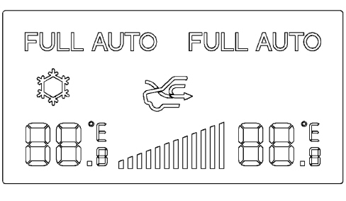
| ... DATA ERROR - CROPPED TEXT | Ошибка данных - Текст обрезан ... |
|---|